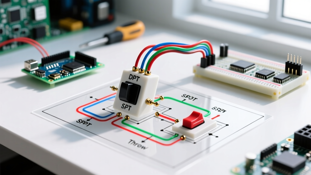

Mastering the Wiring Diagram for a Toggle Switch in Motor Control
When building custom motorized rigs, DIY electric vehicles, or industrial automation prototypes, the humble toggle switch remains the most reliable manual interface. However, interpreting a wiring diagram for a toggle switch in the context of inductive motor loads is vastly different from wiring a simple resistive lighting circuit. Motors generate massive inrush currents and inductive kickback that can weld undersized switch contacts together in milliseconds.
In this 2026 motor wiring tutorial, we break down the exact terminal mappings, wire gauge selections, and National Electrical Code (NEC) compliance rules for wiring Single Pole Single Throw (SPST) and Double Pole Double Throw (DPDT) toggle switches to DC and AC motors.
Switch Terminology and Motor Load Ratings
Before cutting any wire, you must verify that your toggle switch is rated for inductive or motor loads, not just resistive loads. A switch rated for '20A Resistive' may fail catastrophically at just 5A when switching an inductive motor due to the DC arc or AC phase-shift kickback.
| Switch Type | Terminals | Function | Recommended Model (2026) | Approx. Cost |
|---|---|---|---|---|
| SPST (ON-OFF) | 2 | Simple power interruption | Carling V1D1B60B (20A) | $9 - $14 |
| SPDT (ON-ON) | 3 | Select between two power sources | Carling V4D1B60B | $12 - $16 |
| DPDT (ON-ON) | 6 | Polarity reversal / Forward-Reverse | Cole Hersee 9024 (25A) | $28 - $42 |
According to the NFPA 70 (NEC) Article 430, motor controllers and disconnect switches must be horsepower (HP) rated or capable of handling the locked-rotor current (LRC) of the motor without degradation. Always look for the 'HP' stamp or specific DC motor amp ratings on the switch housing.
Scenario 1: SPST Toggle Switch Wiring (Basic ON/OFF)
The simplest wiring diagram for a toggle switch involves an SPST configuration. This is used when you only need to interrupt the main power feed to a motor controller or a low-draw DC motor (under 15A continuous).
Step-by-Step Wiring Procedure
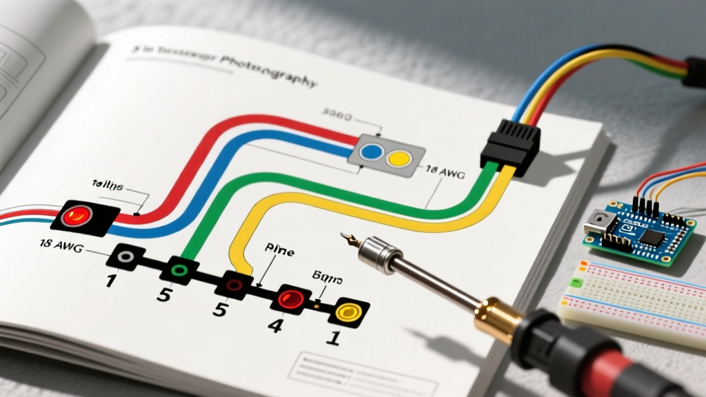
- Calculate Wire Gauge: For a 20A continuous motor draw, NEC Table 310.16 mandates a minimum of 12 AWG THHN/THWN copper wire. For 12V DC applications, upgrade to 10 AWG to mitigate voltage drop over runs longer than 5 feet.
- Prepare the Terminals: Strip exactly 3/8 inch of insulation. Crimp using a Klein Tools 11055 wire stripper and a ratcheting crimp tool to ensure a gas-tight connection on the switch's 1/4-inch quick-connect spades.
- Connect Power In: Run the positive lead from your fused battery source or breaker panel to Terminal 1 (or either terminal on a basic 2-terminal SPST).
- Connect Load Out: Run a wire from Terminal 2 to the positive input of your motor or motor controller.
- Grounding: The motor chassis and negative return must be tied directly to the common ground busbar, bypassing the toggle switch entirely.
Pro-Tip: Always install a flyback diode (like a 1N5408) across the motor terminals if you are switching raw DC inductive loads without a modern electronic motor controller. This clamps the reverse voltage spike and prevents arcing across your toggle switch contacts.
Scenario 2: DPDT Toggle Switch Wiring (Forward / Reverse Control)
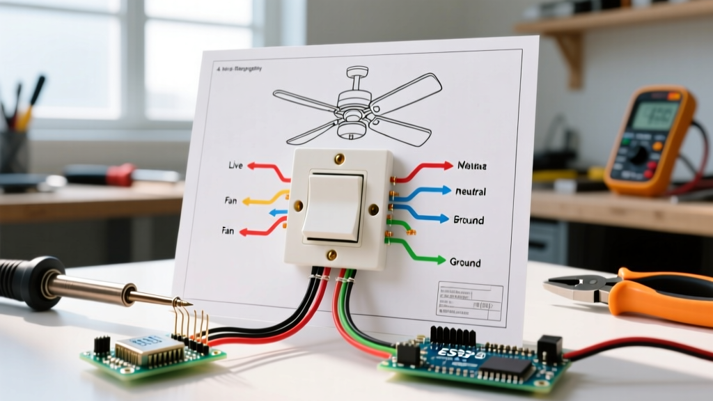
When you need to reverse the direction of a DC motor (e.g., in a winch, a motorized actuator, or a DIY robotics platform), you need a DPDT (Double Pole, Double Throw) switch wired in a polarity-reversing configuration. This specific wiring diagram for a toggle switch utilizes a 'crossover' or 'X' pattern on the bottom terminals.
Terminal Mapping Matrix
A standard DPDT toggle switch has 6 terminals. Facing the back of the switch with the toggle pointing UP:
- Top Row: Terminals 1, 2, 3
- Bottom Row: Terminals 4, 5, 6
- Center Terminals (2 and 5): The 'Common' poles that connect to the motor.
The Crossover Wiring Steps
- Motor Connections: Connect Motor Lead A to Center Terminal 2. Connect Motor Lead B to Center Terminal 5.
- Power Input: Connect Positive (+) Power to Top Terminal 1. Connect Negative (-) Ground to Top Terminal 3.
- The 'X' Crossover: Run a jumper wire from Top Terminal 1 down to Bottom Terminal 6. Run a second jumper wire from Top Terminal 3 down to Bottom Terminal 4.
- Bottom Return Loop: Wire Bottom Terminal 4 to the Negative (-) Ground bus. Wire Bottom Terminal 6 to the Positive (+) Power bus.
How the Logic Works
- Toggle UP: Center terminals (2,5) connect to the top row (1,3). Motor Lead A gets Positive, Motor Lead B gets Negative. Motor spins Forward.
- Toggle DOWN: Center terminals (2,5) connect to the bottom row (4,6). Due to the crossover, Motor Lead A gets Negative, Motor Lead B gets Positive. Motor spins Reverse.
- Center-Off Variant: If you use an ON-OFF-ON DPDT switch (like the Littelfuse/Carling V-Series center-off models), the middle position disconnects both poles, acting as a dynamic brake or hard stop depending on your motor controller.
Failure Modes: Why Toggle Switches Melt on Motor Loads
Even with a correct wiring diagram for a toggle switch, DIYers frequently report melted housings or stuck toggles. This is almost always due to ignoring inductive load physics. According to NEMA MG 1 standards for motor performance, a standard DC motor can draw 500% to 700% of its Full Load Amps (FLA) during startup (Locked Rotor Amps).
Troubleshooting & Prevention Checklist
| Failure Symptom | Root Cause | Engineering Fix |
|---|---|---|
| Toggle physically stuck in ON position | Contact welding from high inrush current arc. | Upgrade to a switch with silver-cadmium oxide (AgCdO) contacts, or use the toggle to trigger a high-amp automotive relay instead. |
| Switch housing melting / hot to touch | Undersized wire gauge or poor crimp causing high resistance. | Verify 12 AWG minimum for 20A. Use adhesive-lined heat shrink (e.g., 3M FP-301) over the crimp to prevent oxidation. |
| Motor stutters or runs hot | Voltage drop across degraded internal switch contacts. | Replace the switch. Never sand or file internal toggle contacts; this removes the factory anti-arc plating. |
Toggle Switch vs. Rotary Cam Switch for High HP Motors
While a toggle switch is perfect for fractional horsepower (1/4 HP to 1/2 HP) DC and AC motors, it reaches its physical limits quickly. If your motor wiring project exceeds 30A continuous or 2 HP at 120VAC, you must abandon toggle switches in favor of Rotary Cam Switches or heavy-duty contactors.
Rotary switches utilize a mechanical 'snap-action' internal spring mechanism that forces the contacts to open and close rapidly, regardless of how slowly the user turns the knob. This drastically reduces the dwell time of the electrical arc. Toggle switches, by contrast, rely entirely on the speed of the user's thumb, making them vulnerable to slow-break arcing on heavy AC inductive loads.
Final Safety and Compliance Directives
When integrating any manual switch into a hardwired motor circuit, ensure you have an appropriately rated overcurrent protection device (OCPD) installed upstream. The OCPD (fuse or breaker) must be sized to protect the wire, while the motor's internal thermal overload or external motor protection relay must be sized to protect the motor. Never rely on a standard thermal-magnetic breaker to protect a motor from prolonged, low-level overloads, as the breaker's trip curve will not react fast enough to prevent winding burnout.
By strictly following this wiring diagram for a toggle switch, utilizing motor-rated components, and respecting the physics of inductive kickback, your DIY motor control panels will deliver years of safe, reliable operation.