
Understanding the Modern Pool Pump Electrical Wiring Diagram
Wiring a pool pump is one of the most critical electrical tasks a homeowner or contractor can undertake. Unlike standard household appliances, pool pumps operate in wet, highly corrosive environments and handle massive inductive loads. Misinterpreting a pool pump electrical wiring diagram doesn't just risk burning out a $1,500 variable speed motor; it introduces severe electrocution hazards. As of 2026, the U.S. Department of Energy mandates that most new dedicated-purpose pool pumps be variable speed models (VSPs), which feature complex digital drive boards rather than simple single-speed induction terminals. According to the Department of Energy's pool pump guidelines, VSPs can reduce energy consumption by up to 70%, but their sensitive microprocessors demand precise voltage delivery and strict adherence to grounding protocols.
This comprehensive tutorial decodes the pool pump electrical wiring diagram for both legacy dual-voltage single-speed motors and modern variable speed drives, ensuring full compliance with NEC Article 680.
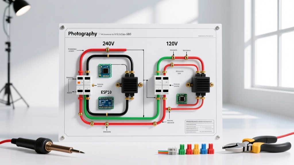
120V vs. 240V: Interpreting the Terminal Block
The first step in any installation is identifying the voltage requirement. While above-ground pools often utilize 120V systems, in-ground pools almost exclusively require 240V circuits to handle the higher horsepower and minimize voltage drop over long conduit runs.
Dual-Voltage Single Speed Motors
Older or replacement single-speed motors (like the Hayward Super Pump or Pentair SuperFlo) typically feature a dual-voltage terminal board. Inside the wiring compartment, you will find a schematic sticker. For 240V operation, the internal switch or jumper must be set to the '230V' position. In this configuration, Line 1 (L1) and Line 2 (L2) connect to the two hot terminals (usually labeled T1 and T4, or L1 and L2), while the neutral wire is capped off and not connected to the motor. For 120V operation, the switch is flipped to '115V', requiring one hot wire, one neutral wire, and a ground.
Variable Speed Pump (VSP) Drive Boards
Modern VSPs, such as the Pentair IntelliFlo VSF (Model 011056), do not use dual-voltage jumpers. They are hardwired strictly for 240V (or 230V nominal). The wiring diagram on the underside of the drive cover will show a 4-terminal block: L1, L2, Ground, and occasionally a dedicated communication terminal for RS-485 automation networks. Connecting 120V to a 240V-only VSP will cause the internal rectifier to fail immediately, voiding the warranty and requiring a $600+ drive replacement.
Component Sizing & NEC Code Matrix
Sizing your breaker and wire correctly is non-negotiable. Pool pumps are considered continuous or heavy inductive loads. The NFPA 70 (National Electrical Code) Article 680.21 outlines specific branch circuit requirements for pool motors. Below is the 2026 standard sizing matrix for copper THWN-2 conductors in PVC conduit.
| Pump Type / HP | Nominal Voltage | GFCI Breaker Size | Min. Wire Gauge (THWN-2) | Conduit Requirement |
|---|---|---|---|---|
| 1.0 HP Single Speed | 240V | 20A (2-Pole GFCI) | 12 AWG | 3/4' PVC Sch 80 |
| 1.5 HP Single Speed | 240V | 20A (2-Pole GFCI) | 12 AWG | 3/4' PVC Sch 80 |
| 2.0 THP Variable Speed | 240V | 30A (2-Pole GFCI) | 10 AWG | 1' PVC Sch 80 |
| 3.0 THP Variable Speed | 240V | 30A (2-Pole GFCI) | 10 AWG | 1' PVC Sch 80 |
Note: As of 2026, a high-quality 30A 2-pole GFCI breaker (such as the Eaton CHFGFI230 or Siemens QFP230GFI) costs between $140 and $180. Never use standard aluminum wire for pool pump circuits; copper is mandatory due to corrosion resistance and termination torque requirements.
Step-by-Step 240V Wiring & GFCI Integration
Follow this exact sequence to wire a 240V variable speed pool pump safely. Always use a calibrated digital multimeter (like the Fluke 117) to verify zero energy before touching terminals.
- Mount the GFCI Breaker: Install the 2-pole GFCI breaker into the main service panel or a dedicated sub-panel. Connect the white pigtail from the breaker directly to the panel's neutral bus bar. This is critical; without the neutral pigtail, the breaker's internal logic board cannot power up or detect ground faults.
- Pull the Conductors: Pull two hot wires (Black and Red), one neutral (White), and one ground (Green or Bare) through the liquid-tight flexible conduit or rigid PVC. While the neutral is not used by the 240V pump motor itself, NEC code often requires it to be pulled through the conduit to the pump's junction box or timer enclosure for future 120V accessories or smart relays.
- Terminate at the Panel: Connect the Black and Red wires to the GFCI breaker load terminals. Torque the terminal screws to the manufacturer's specification (usually 35-40 in-lbs). Connect the Green/Bare ground to the panel's grounding bus bar.
- Terminate at the Pump: Open the pump's wiring compartment. Connect Black to L1, Red to L2, and Green to the Grounding Screw. Crucial Step: Use a torque screwdriver set to 12-14 in-lbs for the pump terminal screws. Under-torqued connections cause micro-arcing, which generates heat, melts the terminal block, and destroys the VSP drive board.
- Seal the Compartment: Apply a bead of marine-grade silicone around the conduit hub entering the pump to prevent moisture ingress, which is the leading cause of GFCI nuisance tripping.
Equipotential Bonding: The Hidden Safety Requirement
Grounding and bonding are not the same thing. Grounding provides a path for fault current to trip the breaker. Bonding connects all metallic components together so that no potential difference (voltage gradient) can exist between them, preventing shock if a person touches the pool water and a metal ladder simultaneously.
NEC Article 680.26(B) mandates that the following parts must be bonded together using a solid 8 AWG bare copper wire:
- All metallic structural parts of the pool shell.
- Underwater lighting shells.
- All metal fittings within 5 feet of the pool (diving stands, ladders).
- The pool pump motor's external bonding lug.
- Any metal decking or coping within 3 feet of the pool edge.
The 8 AWG solid copper bonding wire must be connected to the specialized brass bonding lug located on the outside of the pool pump motor housing. Do not confuse this with the internal green grounding screw. If your pump motor is replaced, ensure the new motor has an intact bonding lug; many cheap aftermarket replacement motors omit this, rendering the installation illegal and unsafe.
Advanced Troubleshooting: GFCI Nuisance Trips & Voltage Drop
Even with a perfect pool pump electrical wiring diagram execution, environmental factors can cause system failures. Here is how to diagnose the two most common VSP issues in 2026.
1. GFCI Nuisance Tripping on Long Conduit Runs
Variable speed pumps contain large capacitors and variable frequency drives (VFDs) that generate high-frequency leakage current. If your conduit run from the panel to the pump exceeds 100 feet, the natural capacitance of the long wires can accumulate this leakage, causing the 5mA GFCI breaker to trip randomly, especially when the pump ramps up to high RPMs.
The Fix: Do not replace the GFCI with a standard breaker (this is a severe code violation and lethal hazard). Instead, consult the U.S. Consumer Product Safety Commission's electrical safety guidelines regarding ground fault protection, and install a specialized VFD-compatible GFCI breaker (like the Siemens QFGA series) designed to filter out high-frequency capacitive leakage while still tripping on dangerous 60Hz ground faults.
2. Voltage Drop and Drive Board Failures
VSP microprocessors are highly sensitive to voltage sag. If the voltage at the pump terminals drops below 216V (a 10% drop from 240V), the drive may fault out, display an 'Under Voltage' error code, or suffer premature capacitor failure. Always calculate voltage drop for runs over 75 feet using the formula: VD = (2 x K x I x L) / CM, where K is 12.9 for copper, I is max amperage, L is one-way length, and CM is the circular mil area of the wire. If you are running a 3.0 THP Pentair IntelliFlo VSF over 150 feet, you must upsize from 10 AWG to 8 AWG or even 6 AWG copper wire to maintain voltage integrity and protect your investment.
Final Safety Verification
Before filling the pump basket with water and priming the system, perform a continuity test between the pump's external bonding lug and the pool's main equipotential bonding grid. The resistance should read less than 1 ohm. Once verified, restore power, allow the GFCI breaker to initialize, and run the pump at 1500 RPM to verify rotation direction and check for any abnormal harmonic humming that might indicate a loose internal terminal connection. Proper adherence to the wiring diagram and NEC codes ensures a safe, efficient, and long-lasting pool circulation system.