
The Hidden Cost of Incorrect Water Pump Wiring
When installing or replacing a submersible or jet pump, misinterpreting the wiring diagram for water pump motors is one of the most common and expensive mistakes DIYers and junior technicians make. A motor rewind for a standard 3HP Franklin Electric submersible motor can easily exceed $850 in 2026, not including the labor to pull the drop pipe. The vast majority of these premature failures are not caused by mechanical wear, but by electrical starvation: specifically, undersized wire gauge leading to excessive voltage drop, or miswired color codes causing start-winding burnout.
This comprehensive reference guide bridges the gap between theoretical schematics and real-world trench work. We will decode standard pump wiring diagrams, establish exact wire gauge requirements based on the National Electrical Code (NEC), and map out the color codes for both 2-wire and 3-wire configurations.
Decoding the Standard Wiring Diagram for Water Pump Motors
Before pulling wire through a well seal, you must identify whether your system utilizes a 2-wire or 3-wire motor configuration. The wiring diagram for water pump setups changes fundamentally between these two architectures.
2-Wire Submersible Pumps (Wire-and-Forget)
In a 2-wire system, the starting relay and run capacitors are hermetically sealed inside the motor housing. The wiring diagram is remarkably simple: you are simply supplying line voltage and a ground. There is no above-ground control box. While this simplifies the wiring diagram for water pump installations, the tradeoff is that if the internal capacitor fails, the entire motor must be pulled from the well and replaced.
3-Wire Submersible Pumps (Control Box Dependent)
A 3-wire system moves the starting components (start capacitor, run capacitor, and relay) to an above-ground control box mounted on the wellhouse wall. The wiring diagram for this setup requires an extra conductor to manage the start winding independently of the main winding. This is the industry standard for motors 1.5 HP and larger because it allows for easier troubleshooting and component replacement without pulling the pump.
Expert Callout: The Control Box Capacitor CheckBefore wiring a new 3-wire pump, always test the capacitors in the control box with a digital multimeter capable of measuring microfarads (µF). A start capacitor reading more than 10% outside its printed µF rating will cause the motor to draw locked-rotor amps (LRA) for too long, tripping the overload switch or melting the starting relay contacts.
Wire Gauge Selection: Sizing for Amps and Distance
The most critical element of any water pump wiring diagram is the wire gauge specification. Sizing wire for a motor is not the same as sizing wire for a standard resistive load like a water heater. According to NEC Article 430, motor branch circuit conductors must be sized at no less than 125% of the motor's Full Load Amps (FLA). Furthermore, because well pumps are often located hundreds of feet from the breaker panel, voltage drop becomes the governing factor, frequently requiring you to upsize the wire beyond the NEC minimum ampacity requirements.
The 5% Voltage Drop Rule
Submersible motors are highly sensitive to low voltage. A 5% drop in voltage results in a 10% drop in starting torque. If your 230V motor receives only 218V at the terminals, it will struggle to start, overheat, and eventually fail. As of 2026, with copper prices stabilizing around $4.10 per pound, the material cost to upsize from 10 AWG to 8 AWG direct-burial pump cable is roughly $0.85 per foot—a minor premium that guarantees motor longevity.
230V Single-Phase Pump Wire Sizing Matrix
The following table provides the maximum one-way run length for copper wire to maintain a voltage drop of less than 5% at 230V. Always use the next wire size up if your run length exceeds the maximum distance.
| Motor Size (HP) | Full Load Amps (FLA) | 14 AWG Max Run | 12 AWG Max Run | 10 AWG Max Run | 8 AWG Max Run | 6 AWG Max Run |
|---|---|---|---|---|---|---|
| 1/2 HP | 6.0 A | 220 ft | 350 ft | 560 ft | 890 ft | 1400 ft |
| 3/4 HP | 8.5 A | 150 ft | 240 ft | 390 ft | 620 ft | 990 ft |
| 1.0 HP | 10.0 A | N/R | 200 ft | 330 ft | 530 ft | 840 ft |
| 1.5 HP | 14.0 A | N/R | N/R | 230 ft | 370 ft | 590 ft |
| 3.0 HP | 22.0 A | N/R | N/R | N/R | 240 ft | 380 ft |
Note: N/R (Not Recommended) indicates the wire gauge cannot safely handle the 125% FLA ampacity requirement regardless of distance, per NEC Table 310.16.
Standard Color Codes: Mapping the Conductors
Confusion over wire colors is where the wiring diagram for water pump setups is most frequently misapplied. Submersible pump cable typically features a flat, polyethylene (PE) jacketed design with color-coded THWN-2 conductors inside. However, the colors differ depending on the manufacturer and the motor type.
Franklin Electric 3-Wire Color Code Standard
Franklin Electric, the dominant OEM in the submersible market, utilizes a specific color code for their 3-wire motors that differs slightly from standard NEC branch circuit wiring. According to the Franklin Electric Application Installation Manual (AIM), the drop cable colors map as follows:
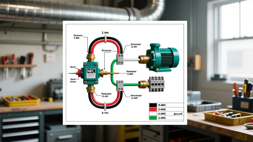
- Black: Main Winding (Line 1)
- Red: Start Winding (Connects to start capacitor/relay in control box)
- Yellow: Common Winding (Line 2 / Neutral return path)
- Green: Equipment Grounding Conductor
Standard NEC 240V Split-Phase Color Code (2-Wire Pumps & Jet Pumps)
For 2-wire submersible pumps, or shallow-well jet pumps like the Goulds Water Technology J5S, you are wiring a standard 240V split-phase circuit. The colors inside standard UF-B or conduit-pulled THHN wire follow strict NEC conventions:
- Black: Hot Leg 1 (120V to ground)
- Red (or White re-identified with black tape): Hot Leg 2 (120V to ground)
- Bare Copper or Green: Equipment Ground
Warning: Never use the white neutral wire as a hot leg for a 240V pump circuit without permanently re-identifying it with black or red electrical tape at both the panel and the disconnect switch, as mandated by NEC 200.7(C).
Step-by-Step: Executing the Submersible Splice
The wiring diagram is only as good as its weakest physical connection. The submersible splice is the most common failure point in well systems. Water intrusion at the splice will cause a ground fault, tripping the GFCI breaker or destroying the motor windings. Follow this exact procedure for a watertight seal:
- Prep the Cable: Strip 4 inches of the flat PE jacket. Strip 3/4 inch of insulation from the individual THWN-2 conductors.
- Stagger the Splices: Cut the conductors at staggered lengths (e.g., 3", 4", 5") so the bulky wire nuts or crimps do not sit directly adjacent to one another, reducing the overall diameter of the splice bundle.
- Make the Connection: Use silicone-filled, gel-crimp wire connectors (e.g., 3M Scotchlok UR2 or direct burial twist-on connectors). Do not use standard indoor wire nuts.
- Adhesive Heat Shrink: Slide 3/8-inch dual-wall, adhesive-lined heat shrink tubing over each individual splice. Apply heat until the internal epoxy sealant squeezes out the ends.
- Resin Encapsulation: For the ultimate seal, place the entire spliced section into a 3M Scotchcast 82-G1 or Franklin Electric SubDrop resin kit. Mix the two-part polyurethane resin and pour it into the mold. This creates a solid, waterproof block rated for continuous submersion up to 300 feet.
Common Failure Modes & Troubleshooting
Even with a perfect wiring diagram for water pump adherence, systems fail. Here is how to diagnose electrical faults using a multimeter and a megohmmeter (Megger):
- Motor Hums but Won't Start: Usually a failed start capacitor in the control box (3-wire systems) or a stuck impeller. Check the capacitor for bulging, or test it with a capacitance meter. If the capacitor is good, the pump may be mechanically bound by sand or debris.
- Breaker Trips Instantly (Short Circuit): Indicates a severed drop cable or a splice failure where conductors are touching. Disconnect the pump at the control box and test continuity between Black, Red, and Yellow wires. There should be infinite resistance (OL) between them.
- Breaker Trips After 3-5 Seconds (Ground Fault): Water has entered the motor or the splice. Perform an insulation resistance test (Megger test) at 500V DC between the motor windings and the ground wire. A healthy motor will read >20 Megohms. A reading below 2 Megohms indicates compromised winding insulation or a wet splice.
Final Thoughts on Pump Wiring
Successfully executing a wiring diagram for water pump installations requires respecting both the schematic logic and the physical realities of voltage drop and waterproofing. By sizing your wire based on distance rather than just ampacity, strictly adhering to OEM color codes, and utilizing resin-encapsulated splices, you ensure the system will operate reliably for the next 10 to 15 years without requiring a costly well pull.