
The Blueprint Phase: Why Diagrams Dictate Success
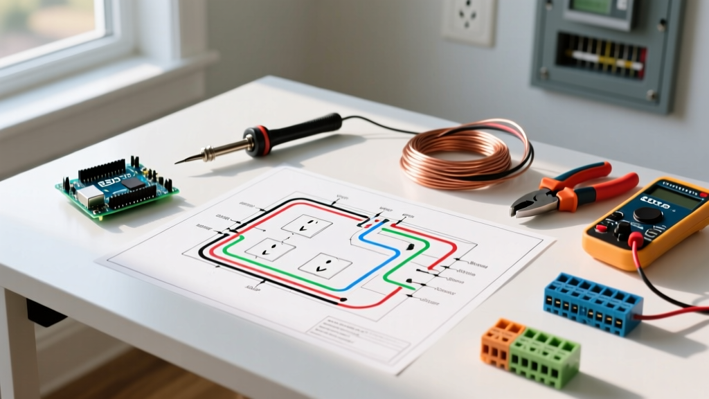
The most critical phase of any home electrical project happens before a single wire is pulled or a drywall saw is fired up. For homeowners tackling renovations, additions, or subpanel installations, mastering DIY electrical wiring diagrams is the difference between a safe, code-compliant system and a hazardous fire risk. A wiring diagram is not just a map; it is a mathematical and physical contract with the National Electrical Code (NEC). In 2026, with the widespread adoption of smart home integrations and higher continuous loads from EV chargers and heat pumps, precise planning via schematics is non-negotiable.
This installation planning guide will teach you how to decode standard schematics, perform mandatory load calculations, and translate 2D diagrams into 3D physical routes while avoiding the most common DIY failure modes.
Decoding Standard Electrical Symbols
Before you can plan a route, you must fluently read the language of the diagram. Electrical blueprints rely on standardized NEMA and ANSI symbols. Misinterpreting a symbol can lead to severe code violations, such as missing arc-fault protection in a bedroom.
| Symbol Representation | Component Description | NEC Reference (2023/2026 Cycle) |
|---|---|---|
| Circle with 'G' inside | GFCI (Ground Fault Circuit Interrupter) Receptacle | Article 210.8 (Wet/Damp locations) |
| Circle with 'A' inside | AFCI (Arc Fault Circuit Interrupter) Breaker/Receptacle | Article 210.12 (Dwelling unit bedrooms/living areas) |
| Switch with '3' or '4' | 3-Way or 4-Way Traveler Switch | Article 404.2 (Switch connection in ungrounded conductor) |
| Square with 'D' inside | Disconnect Switch / Isolation Panel | Article 430.102 (Motor disconnects) |
| Circle with crosshatch | Ceiling Fan Rated Junction Box | Article 314.27 (Support for ceiling fans over 35 lbs) |
Step-by-Step Installation Planning Workflow
Translating DIY electrical wiring diagrams into a physical installation requires a rigid, step-by-step methodology. Do not skip the mathematical verification steps.
Step 1: Load Calculation and Circuit Sizing
Every circuit on your diagram must be verified against the NEC 80% rule for continuous loads (loads expected to run for 3 hours or more). If your diagram shows a dedicated 20-amp circuit for a basement dehumidifier and a sump pump, you must calculate the actual wattage.
- Formula: Watts / Volts = Amps.
- Example: A 1,500W space heater on a 120V circuit draws 12.5 Amps. On a 15A breaker, this is 83% of the capacity, violating the 80% continuous load rule (12A max). You must upgrade the diagram to specify a 20A breaker and 12 AWG wire.
According to the National Fire Protection Association (NFPA), Article 220 dictates that general lighting loads for dwellings are calculated at 3 volt-amperes per square foot. Always cross-reference your diagram's square footage against this baseline.
Step 2: Mapping the Physical Route and Derating
Diagrams show logical connections, not physical realities. When planning the physical route through studs and joists, you must account for ambient temperature and conductor bundling. If your diagram routes four current-carrying conductors (e.g., two 12/2 Romex cables) through a single bored hole in a top plate, NEC Article 310.15 requires derating.
- 4 to 6 conductors in a bundle: Multiply ampacity by 80%.
- 7 to 9 conductors: Multiply ampacity by 70%.
Expert Note: While 12 AWG THHN wire is rated for 30A in the 90°C column, NEC 240.4(D) strictly limits overcurrent protection for 12 AWG copper to 20A, regardless of derating math. Always plan your physical routes to minimize bundling to avoid unnecessary voltage drop and heat accumulation.
Step 3: Voltage Drop Verification
Long runs depicted on DIY electrical wiring diagrams often hide voltage drop issues. The NEC recommends a maximum 3% voltage drop for branch circuits. Use this formula during the planning phase:
VD = (2 × K × L × I) / CM
Where K = 12.9 (Copper), L = One-way length in feet, I = Current in Amps, CM = Circular Mils (6,530 for 12 AWG).
If your diagram shows a 12 AWG circuit running 80 feet to a detached garage subpanel drawing 16 Amps, the voltage drop is 5.06V (4.2%). This fails the 3% guideline. Your installation plan must override the diagram and specify 10 AWG wire for the main feeder run.
Common DIY Diagram Pitfalls and Failure Modes
Even well-drawn schematics can lead to physical installation errors if the DIYer ignores spatial constraints. Here are the most frequent failure modes encountered during the rough-in phase.
Box Fill Violations (NEC 314.16)
Diagrams rarely show the physical volume of junction boxes. You must calculate box fill manually. Each 12 AWG wire counts as 2.25 cubic inches. A standard single-gang plastic nail-on box is 14 cubic inches. If you push two 12/2 cables into this box, you have 4 current-carrying wires, 1 ground allowance, and 1 device yoke allowance (6 total). 6 × 2.25 = 13.5 cubic inches. You are at 96% capacity. If you add a pigtail, you will violate the box fill limit, causing wires to crush against the device terminals and creating a high-resistance hot spot.
Shared Neutral Dangers (MWBC)
Multi-Wire Branch Circuits (MWBC) are common on DIY diagrams to save wire. They use two hot wires (on opposite phases) sharing a single neutral. Critical Safety Rule: If you plan to install an MWBC, the diagram must explicitly call out a 2-pole breaker or handle-tied single-pole breakers (NEC 210.4). If a DIYer replaces a handle-tied breaker with two independent singles during a future panel swap, the shared neutral will carry the sum of both hots (up to 40A on a 14 AWG neutral), resulting in a catastrophic neutral fire. For modern 2026 installations, it is highly recommended to abandon MWBCs in favor of dedicated 12/2 runs to eliminate this risk entirely.
Essential Tools for Diagram Translation
To execute the physical installation based on your diagrams, you need precision tools. Do not rely on cheap multimeters for load verification.
- Klein Tools CL800 Clamp Meter (~$135): Essential for verifying actual current draw against your diagram's planned load without breaking the circuit.
- Greenlee 13/16" Self-Feed Wood Bit (~$45): Required for boring joists. NEC 300.4 mandates that holes bored in studs must be at least 1.25 inches from the edge. Using a massive self-feed bit ensures clean holes without splintering the structural edges.
- Southwire 12/2 NM-B (Romex) (~$0.85/ft in 2026): Always buy 12 AWG for 20A circuits. While 14 AWG is cheaper, the voltage drop and future-proofing benefits of 12 AWG far outweigh the $0.25/ft difference.
Frequently Asked Questions (FAQ)
Can I use a 15A receptacle on a 20A circuit shown in my diagram?
Yes. NEC 210.21(B)(3) explicitly allows 15A duplex receptacles on a 20A circuit, provided there is more than one receptacle on the circuit (a duplex counts as two). However, if the diagram shows a single dedicated receptacle for a specific 20A appliance, you must use a 20A receptacle (identified by the T-shaped neutral slot).
How do I handle smart switches on older wiring diagrams?
Most older home diagrams lack a neutral wire at the switch box. Modern smart switches (like the Lutron Caseta or GE Enbrighten Z-Wave) require a neutral to power their internal radios. If your diagram shows a simple switch loop (only a hot and a switched hot), you must either pull a new 14/3 or 12/3 cable to include a neutral, or specifically source "no-neutral required" smart switches, which are generally limited to incandescent or specific dimmable LED loads.
What is the safest way to verify my DIY diagram before energizing?
Before turning on the main breaker, perform a dead-front continuity test. The Occupational Safety and Health Administration (OSHA) emphasizes lockout/tagout and verification procedures. Use your multimeter in continuity mode to check for dead shorts between the hot bus bar and the neutral/ground bars. If the meter beeps, you have a hard short that will cause an explosive arc flash upon energization. Trace the diagram back to find the fault.
For further reading on residential electrical safety and energy efficiency baselines, refer to the U.S. Department of Energy's Electricity Basics guide. Proper planning using accurate DIY electrical wiring diagrams ensures your home remains safe, efficient, and fully compliant with modern electrical codes.