
Introduction: Safety First in Smart HVAC Integration
Upgrading to a smart thermostat is one of the most effective ways to improve home energy efficiency, but it introduces new variables to your HVAC control circuit. The Nest Learning Thermostat 3rd Generation (Model T3007ES / GA01319-US) remains a benchmark device in 2026, celebrated for its learning algorithms and sleek design. However, treating its installation as a simple 'plug-and-play' swap is a dangerous misconception. Improper wiring doesn't just result in a blank screen; it can lead to blown control board fuses, damaged contactor coils, and severe fire hazards.
This guide provides a comprehensive, safety-focused wiring diagram for Nest Thermostat 3rd Generation installations, strictly aligned with the National Electrical Code (NEC). We will cover Lockout/Tagout (LOTO) procedures, Class 2 circuit compliance, the critical role of the C-wire, and high-voltage hazard identification.
Pre-Installation: Lockout/Tagout (LOTO) & Verification
Before removing your old thermostat faceplate, you must de-energize the system. Relying solely on the thermostat's internal switch is a violation of basic electrical safety protocols.
- Locate the Dedicated Breaker: Identify the 120V/240V breaker supplying the air handler or furnace in your main electrical panel. Switch it to the OFF position.
- Disconnect the Local Service Switch: NEC Article 430.102 requires a disconnecting means in sight from the motor controller. Turn off the standard 120V toggle switch located on or immediately adjacent to the furnace/air handler.
- Verify Zero Energy: Use a Category III (CAT III) Non-Contact Voltage Tester (NCVT) at the thermostat wires. Follow up with a digital multimeter set to AC Voltage (V~), testing between the R (power) wire and the C (common) or W (heat) wire. The reading must be exactly 0.0V before proceeding.
NEC Article 725: Class 2 Circuit Compliance
Thermostat wiring falls under NFPA 70 (NEC) Article 725, which governs Class 1, Class 2, and Class 3 remote-control, signaling, and power-limited circuits. The Nest 3rd Gen operates on a 24VAC Class 2 circuit.
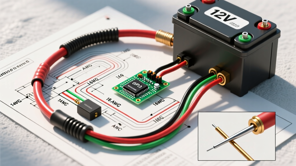
Code Requirement: Class 2 circuits are power-limited to prevent fire initiation and provide shock protection. The 24VAC transformer supplying your HVAC control board must be inherently power-limited or protected by an overcurrent device rated at no more than 5 amps. Furthermore, the cable used must be rated as CL2 or CL3 (e.g., 18 AWG solid copper with a PVC jacket rated for 300V and 75°C) to prevent fire propagation inside wall cavities.
Never run standard 14 AWG or 12 AWG NM-B (Romex) line-voltage cable to a thermostat location unless it is specifically stepping down through a junction box and a Class 2 transformer at the thermostat location—a rare and outdated practice in modern residential construction.
The C-Wire Conundrum: Power Stealing vs. Continuous Loads
Google markets the Nest 3rd Generation as capable of operating without a Common (C) wire. While technically true for some systems, relying on 'power stealing' is a leading cause of HVAC equipment failure and violates the spirit of NEC continuous load guidelines.
How Power Stealing Works (and Fails)
Without a C-wire, the Nest completes its 24VAC circuit by passing a trickle of current (typically 10-20 milliamps) through the heating (W) or cooling (Y) relay coils when the system is idle. This 'steals' power to charge the internal lithium-ion battery. However, if the relay coil's resistance is too low, or if the system uses sensitive solid-state relays, this trickle current can cause:
- Contactor Chatter: The AC compressor contactor rapidly engages and disengages, welding the contacts or burning out the compressor motor.
- Micro-Shorts: Premature failure of the HVAC control board's triacs.
- Boiler Lockouts: Modern condensing boilers (e.g., Viessmann, Navien) detect the parasitic draw as a fault and trigger hard lockouts.
The Safety Mandate: Always install a dedicated 18 AWG C-wire connected to the 'C' terminal on both the HVAC control board and the Nest baseplate. If your existing thermostat cable lacks an unused wire, use a code-compliant Add-A-Wire kit (like the Fast-Stat Common Maker, ~$25) or run a new 18/5 CL2 cable.
Wiring Diagram & Terminal Mapping for Nest 3rd Gen
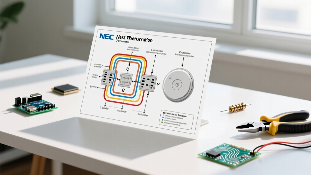
Below is the definitive terminal mapping for standard single-stage and two-stage forced air systems. Ensure wire strands are trimmed to exactly 1/4 inch before inserting them into the Nest baseplate terminals to prevent stray strands from causing a dead short between adjacent pins.
| Nest Terminal | Standard Wire Color | Function & Safety Notes |
|---|---|---|
| Rc | Red (R) | 24VAC Power for Cooling. If only one R wire exists, insert into Rc. The Nest internally bridges Rc and Rh. |
| Rh | Red (R) | 24VAC Power for Heating. Used in dual-transformer systems (e.g., separate boiler and AC). |
| C | Blue or Black | Common Wire. Completes the 24VAC circuit. Mandatory for system longevity and code compliance. |
| W1 | White | Stage 1 Heat. Energizes the gas valve or heat strip relay. Max load: 1A (ensure control board handles the rest). |
| W2 | White w/ Stripe | Stage 2 Heat. For two-stage gas furnaces or backup electric heat strips. |
| Y1 | Yellow | Stage 1 Cooling. Energizes the outdoor condenser contactor coil. |
| Y2 | Yellow w/ Stripe | Stage 2 Cooling. Rare in residential; used in high-end dual-compressor systems. |
| G | Green | Indoor Blower Fan. Energizes the blower relay independently of heating/cooling. |
| O/B | Orange or Dark Blue | Heat Pump Reversing Valve. 'O' for Rheem/Ruud (energize in cooling), 'B' for Carrier/Trane (energize in heating). |
| AUX / * | Various | Used for whole-home humidifiers, dehumidifiers, or emergency heat (E) on heat pumps. |
Critical Hazard: Identifying Line-Voltage Systems
The most catastrophic mistake a DIYer can make is wiring a 120V or 240V line-voltage system to a 24VAC Nest Thermostat. Doing so will instantly destroy the thermostat, melt the wall plate, and create an immediate arc-flash and fire hazard.
According to the U.S. Department of Energy, line-voltage thermostats are typically used for electric baseboard heaters, in-wall fan heaters, and radiant floor heating systems.
How to Identify Line-Voltage Wiring:
- Wire Gauge: Line-voltage systems use thick 14 AWG or 12 AWG solid copper wire (the same thickness as standard wall outlet wiring), not the thin 18 AWG stranded/solid wire used for 24V systems.
- Wire Nuts: If the wires behind your old thermostat are connected via wire nuts rather than low-voltage terminal screws, it is almost certainly line-voltage.
- Thermostat Labels: Look for warning labels on the old thermostat stating '120/240 VAC' or 'Line Voltage Only'.
If you have a line-voltage system, the Nest 3rd Generation is incompatible. You must use a line-voltage smart thermostat (like the Mysa or Sinopé) or install a heavy-duty 24VAC isolation relay (e.g., Honeywell RA410A) to step down the control signal safely.
Overcurrent Protection: The 3A Control Board Fuse
Modern HVAC Integrated Furnace Control (IFC) boards protect the 24VAC transformer secondary winding using a standard 3-Amp ATO (Automotive) blade fuse, usually colored violet or purple. This fuse is your first line of defense against a dead short at the thermostat.
Common Failure Mode: If the bare copper strands of the 'R' (power) wire and 'C' (common) wire touch each other behind the Nest baseplate while the system is energized, it creates a dead short. This will instantly blow the 3A fuse on the control board, killing all power to the thermostat and the indoor blower.
Safety Protocol: Always keep a pack of 3A ATO fuses (under $5 for a multi-pack) in your HVAC toolkit. If your Nest screen goes blank immediately upon restoring power, do not repeatedly reset the breaker. Turn the power off, remove the Nest faceplate, inspect the terminal block for stray wire strands, and replace the blown 3A fuse on the furnace control board.
Transformer Sizing and Continuous Load Calculations
Standard residential HVAC transformers are rated at 40VA (Volt-Amps). At 24VAC, this equates to a maximum continuous current of roughly 1.66 Amps (40 / 24 = 1.66).
The Nest 3rd Gen draws approximately 150mA to 250mA depending on Wi-Fi activity and screen brightness. While this seems negligible, it must be added to the load of the gas valve (approx. 0.5A), the blower relay (approx. 0.3A), and any connected smart humidifiers. If you exceed the 40VA limit, the transformer will overheat, its internal thermal cutoff will trip, or the windings will melt.
The Fix: If you are installing a Nest 3rd Gen alongside smart zoning dampers or a powered humidifier, upgrade your HVAC transformer from 40VA to a 75VA model (such as the Honeywell AT72D1683, ~$35). This ensures the system operates well within the safe thermal limits defined by UL and NEC standards.
Summary of Best Practices for 2026
Installing a smart thermostat is an exercise in low-voltage circuit management. By adhering to NEC Article 725, mandating a dedicated C-wire, verifying wire gauges to prevent line-voltage catastrophes, and ensuring proper overcurrent protection, you guarantee both the safety of your home and the longevity of your HVAC equipment. Always prioritize verified electrical isolation and precise wire termination over speed during installation.