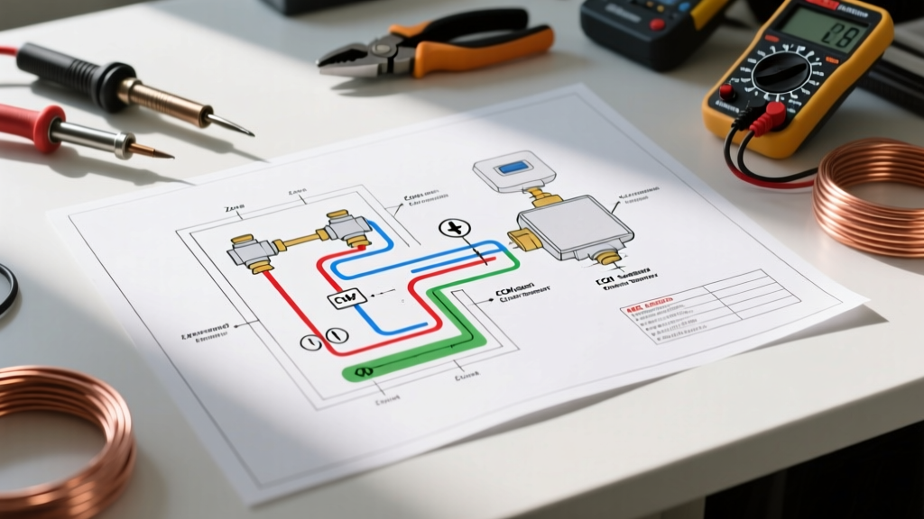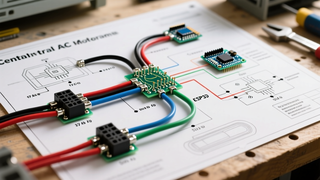

Integrating Residential HVAC into Mobile Platforms
As the luxury Class A motorhome, custom skoolie, and expedition vehicle markets evolve in 2026, builders are increasingly abandoning noisy, inefficient rooftop RV air conditioners in favor of residential-style ducted systems. However, interpreting and executing a wiring diagram for central AC unit installations in a mobile, DC-based environment is one of the most complex electrical challenges an RV DIYer or professional upfitter can face. Unlike standard 120V rooftop units, a 1.5-ton residential central ducted system (such as the Pioneer 18,000 BTU or Senville SENA series) demands 240V for the exterior condenser compressor and 120V for the interior air handler blower.
This guide breaks down the exact electrical architecture required to safely wire a split-phase central air conditioning system into a 48V DC mobile power matrix, ensuring compliance with both the National Electrical Code (NEC) and Recreation Vehicle Industry Association (RVIA) standards.
The 240V Split-Phase Challenge in Vehicles
Standard vehicle battery banks operate at 12V, 24V, or 48V DC. To power a residential central AC, you must invert this DC power to AC. The primary hurdle is that most high-capacity marine and RV inverters, like the widely used Victron MultiPlus-II 48/5000, natively output only 120V AC. If you attempt to wire a 240V condenser directly to a 120V inverter, the compressor will instantly fail or trip the internal overload.
To solve this, the wiring diagram for central AC unit setups in large motorhomes requires a 120/240V Autotransformer. The autotransformer takes the 120V output from the inverter and steps it up to create a 120/240V split-phase output, perfectly mimicking the shore power or residential grid required by the HVAC control board.
Component Sizing & Cost Matrix (2026 Estimates)
| Component | Specification / Model | Estimated Cost (2026) | Purpose |
|---|---|---|---|
| Inverter/Charger | Victron MultiPlus-II 48/5000/70-50 | $2,150 | DC to 120V AC inversion |
| Autotransformer | Victron 120/240V - 100A | $680 | Creates 240V split-phase |
| Soft Start Kit | Micro-Air EasyStart PRO | $340 | Reduces compressor LRA by 70% |
| Battery Bank | 48V 280Ah LiFePO4 (Server Rack) | $1,400 | Provides ~14kWh usable capacity |
| Total Electrical Integration | Wiring, Breakers, Fuses, Lugs | $850 - $1,200 | Infrastructure & safety devices |
Step-by-Step Wiring Procedure
Executing the wiring diagram for central AC unit integration requires strict separation between the high-current DC side and the split-phase AC side. Below is the professional workflow for a 48V system.
1. The DC Architecture (Battery to Inverter)
The inverter will pull massive current when the AC compressor kicks on. For a 5,000VA inverter on a 48V bank, the continuous draw can exceed 100A, with surge spikes hitting 200A.
- Wire Gauge: Use 2/0 AWG Class K fine-strand welding cable. Do not use solid THHN wire for DC battery connections; vehicle vibration will cause solid wire to fatigue and snap.
- Overcurrent Protection: Install a 250A Class T fuse within 18 inches of the battery bank positive terminal. Class T fuses are mandatory for lithium banks due to their high AIC (Ampere Interrupting Capacity) rating, which safely handles the massive fault currents lithium batteries can produce.
- Shunt Installation: Wire a Victron SmartShunt 500A on the negative lead to monitor real-time DC voltage sag during compressor startup.
2. Creating Split-Phase AC (Inverter to Autotransformer)
The 120V AC output of the MultiPlus-II is wired directly to the input of the Autotransformer. The autotransformer's center-tap neutral must be bonded to the vehicle's AC ground bus bar. This creates two 120V legs (L1 and L2) that are 180 degrees out of phase, yielding 240V across them.
3. Wiring the Exterior Condenser Unit
The condenser houses the compressor and requires the 240V supply.
- Wire Type: 10 AWG THHN/THWN-2 stranded wire, pulled through 3/4-inch flexible liquid-tight metallic conduit to protect against road debris and moisture.
- Breaker Sizing: Install a 30A double-pole breaker in the main AC distribution panel. Both L1 and L2 must be switched simultaneously.
- Disconnect: A 60A unfused AC disconnect box must be mounted within sight of the condenser unit, per NEC Article 440.
4. Wiring the Interior Air Handler & Control Board
The interior blower motor and control board typically operate on 120V. Wire this from L1 and Neutral using 14 AWG stranded wire on a 15A single-pole breaker.
Control Wiring and Thermostat Routing
One of the most frequently overlooked aspects of the wiring diagram for central AC unit setups in vehicles is the low-voltage control wiring. The 24V AC control signals traveling from the interior thermostat to the air handler and out to the condenser contactor are highly susceptible to Electromagnetic Interference (EMI) generated by the inverter's high-frequency switching.
Expert Tip: Never run 18 AWG thermostat wire parallel to your 2/0 AWG DC inverter cables. If they must cross, do so at a strict 90-degree angle. Always use shielded 18 AWG control cable in mobile environments, grounding the drain wire at the air handler control board only to prevent ground loops.
RVIA Compliance and Vehicle Grounding
Wiring a residential HVAC system in a vehicle blurs the line between residential NEC codes and mobile RVIA standards. According to the Recreation Vehicle Industry Association (RVIA) standards, the vehicle chassis must never be used as a return path for AC current. Furthermore, the National Fire Protection Association (NFPA) outlines specific grounding requirements in NEC Article 551 for Recreational Vehicles.
- AC Grounding: All non-current-carrying metal parts of the central AC system (condenser casing, air handler chassis, autotransformer case) must be bonded to the main AC ground bus bar using a minimum 8 AWG bare copper wire.
- Neutral-to-Ground Bond: In an RV, the neutral-to-ground bond must only occur at one point: the inverter/charger's internal transfer switch when operating on shore/generator power, or via the inverter's internal relay when inverting. Never bond neutral to ground at the HVAC sub-panel.
- Vibration Mitigation: All terminal lugs must be crimped with a calibrated hydraulic crimper and sealed with adhesive-lined heat shrink. Use split-lock washers and apply Loctite 222 (low-strength threadlocker) to all bus bar and breaker terminal screws to prevent loosening from highway vibration.
Troubleshooting Common Vehicle-Specific Failures
Even with a perfect wiring diagram for central AC unit execution, mobile environments introduce unique failure modes.
Compressor Locked Rotor & Inverter Overload
The Symptom: The inverter alarms and shuts down the moment the thermostat calls for cooling, or the AC control board throws a high-pressure/locked rotor error code.
The Fix: Residential compressors have a massive Locked Rotor Amp (LRA) draw, sometimes exceeding 90A for a fraction of a second. A 5,000VA inverter cannot sustain this surge. You must install a Micro-Air EasyStart PRO soft-start device directly inside the condenser's electrical access panel. This device learns the compressor's startup profile and feeds power in micro-steps, reducing the surge current by up to 70%, allowing a 5kVA inverter to easily start a 1.5-ton compressor.
Voltage Sag and Control Board Resets
The Symptom: The interior air handler blower runs, but the exterior condenser never kicks on, or the smart thermostat screen flashes and reboots randomly.
The Fix: This is almost always caused by DC voltage sag. When the inverter pulls heavy current, if the DC wire run is too long or the lugs are loose, the 48V bank can sag below the inverter's low-voltage disconnect threshold (typically 44V). Check your SmartShunt logs. If voltage drops below 46V under load, upgrade your DC cabling to 4/0 AWG or add a second parallel battery bank to reduce internal resistance.
Final Safety Verification
Before applying power, verify every connection against the Victron Energy Wiring Unlimited guide, which serves as the gold standard for mobile split-phase electrical architectures. Use a digital multimeter to confirm continuity between all ground points and the chassis bonding strap. Once powered, measure the voltage across L1 and L2 at the condenser disconnect; it should read exactly 240V (+/- 2V). Proper execution of this wiring diagram ensures your mobile central AC will provide silent, residential-grade cooling whether you are parked at a luxury RV resort or boondocking off-grid in the desert.