
Decoding the Car Aircon Electrical Wiring Diagram: A Motor-Centric Approach
Automotive HVAC systems have undergone a radical transformation. While legacy vehicles relied on simple 12V relay loops and belt-driven clutches, modern platforms—especially the surge of EVs and hybrids dominating the 2026 market—utilize complex CAN-bus networks and high-voltage inverters. However, whether you are diagnosing a failing Denso 10PA17C clutch coil on a 2018 ICE vehicle or tracing a PWM signal to an electronic control valve (ECV) on a newer model, the ability to read a car aircon electrical wiring diagram remains the foundational skill for any DIYer or technician.
This guide bypasses basic fluff and dives deep into the motor wiring architecture of automotive air conditioning systems. We will trace power flows, decode schematic symbols, and provide exact multimeter testing parameters for compressor and blower motor circuits.
Core Components in the Schematic
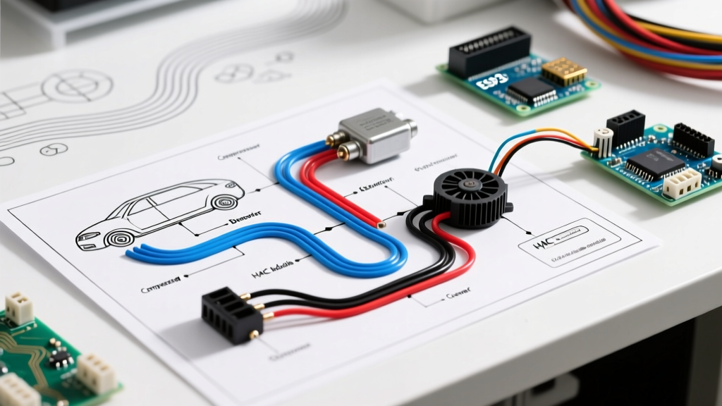
Before tracing a fault, you must identify the primary actors in the wiring diagram. A standard internal combustion engine (ICE) A/C circuit revolves around these critical nodes:
- HVAC Control Head / BCM: The brain. In modern vehicles, the Body Control Module (BCM) processes the A/C request via multiplexed data lines rather than direct hardwiring.
- Pressure Transducer: Replaces legacy binary switches. Outputs a variable voltage signal (typically 0.5V to 4.5V) to the ECU, representing system pressure from 0 to 450+ PSI.
- Compressor Clutch Relay: A standard ISO mini-relay. Pins 30 and 87 handle the high-current load (usually 14 AWG wire), while pins 85 and 86 handle the low-current control circuit (18-20 AWG).
- Compressor Clutch Coil / ECV: The electromagnetic actuator that engages the swashplate or adjusts the displacement angle.
- Blower Motor FET Module: The modern replacement for resistor packs, utilizing Field Effect Transistors to modulate blower speed via a Pulse Width Modulation (PWM) signal.
Tracing the 12V Compressor Clutch Circuit
When the A/C is commanded ON, the electrical sequence follows a strict logical path. Understanding this flow is crucial when using a car aircon electrical wiring diagram to isolate a dead compressor.
- Request Initiation: The HVAC module sends a CAN-bus message to the Engine Control Unit (ECU) requesting A/C engagement.
- ECU Validation: The ECU checks wide-open throttle (WOT) status, engine coolant temperature, and the A/C pressure transducer signal. If pressure is between 35 PSI and 420 PSI, the ECU grounds the control side (Pin 85) of the A/C compressor relay.
- Relay Activation: With Pin 86 receiving constant 12V (ignition-run) and Pin 85 grounded, the relay coil energizes. This closes the internal switch between Pin 30 (Battery 12V) and Pin 87 (Output to clutch).
- Clutch Engagement: 12V travels through a 14 AWG wire to the compressor clutch coil. The coil generates a magnetic field, pulling the friction plate against the pulley, locking it to the compressor shaft.
Fixed Clutch vs. Variable Displacement ECV (2026 Landscape)
One of the most common mistakes when reading a wiring diagram is assuming all compressors use a simple on/off 12V clutch. Modern variable displacement compressors use an Electronic Control Valve (ECV). Applying 12V directly to an ECV will destroy its internal micro-solenoid.
| Feature | Fixed Clutch Compressor (Legacy/Standard) | Variable Displacement w/ ECV (Modern) |
|---|---|---|
| Actuator Type | Electromagnetic friction clutch coil | d>Proportional solenoid valve (ECV) |
| Wiring Diagram Signal | Constant 12V DC (On/Off) | PWM Signal (12V, 100Hz - 1000Hz variable duty cycle) |
| Resistance Spec | 3.5 to 4.5 Ohms | 10.0 to 14.0 Ohms (typically) |
| Common Failure Mode | Clutch air gap too wide; coil burns out | ECV solenoid stuck; wiring harness chafing at firewall |
| Replacement Cost (Part) | $45 - $85 (Clutch coil assembly) | $65 - $120 (ECV solenoid valve) |
Blower Motor Wiring: The Shift to FET Modules
The cabin blower motor is the highest current-drawing component in the HVAC system, often pulling 15 to 20 amps on high speed. Legacy diagrams show a blower motor resistor pack using varying lengths of nichrome wire to drop voltage. In 2026, almost all vehicles use a Blower Motor Control Module (FET).
Diagnosing the FET Module Wiring
If your blower motor only works on high or is completely dead, consult the wiring diagram for the FET module. You will typically find 4 pins:
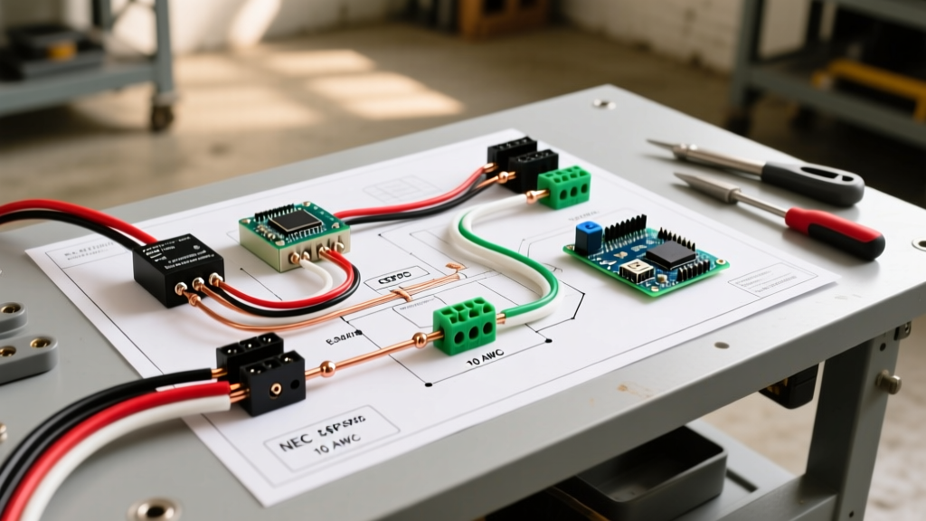
- Pin 1 (B+): Heavy gauge (10 AWG) constant 12V from the battery via a fusible link.
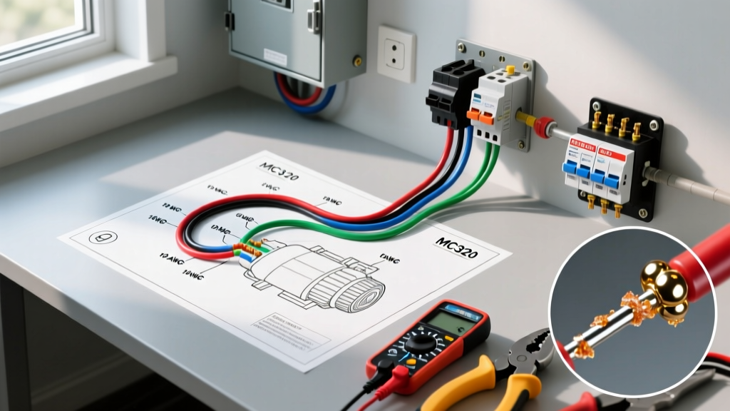
- Pin 2 (Ground): Heavy gauge (10 AWG) chassis ground. Pro Tip: Perform a voltage drop test here. A reading over 0.1V indicates a corroded ground ring terminal.
- Pin 3 (PWM Signal): Low voltage signal from the BCM. Ranges from 2V (low speed) to 10V (high speed).
- Pin 4 (Feedback/Enable): A 5V reference signal confirming the module is online and communicating back to the BCM.
Using an oscilloscope or a high-end multimeter with frequency capture, verify the PWM signal on Pin 3. If the BCM is sending the PWM signal and the FET has good power and ground, but the motor isn't spinning, the FET module's internal transistor has failed and requires replacement.
High-Voltage EV Compressors: A Critical Safety Warning
WARNING: Electric Vehicles (EVs) and PHEVs do not use belt-driven 12V compressors. They utilize 3-phase AC motors driven by high-voltage (300V to 800V) inverters. The wiring diagrams for these systems feature bright orange cabling. Never probe, back-probe, or attempt to repair orange HV A/C compressor wiring without specialized Category III/IV PPE and HV certification. Refer to SAE International safety standards for proper lockout/tagout procedures before servicing EV HVAC systems.
Real-World Troubleshooting: The Voltage Drop Method
Amateurs use test lights; professionals use voltage drop testing. When your car aircon electrical wiring diagram shows that power should be reaching the clutch coil, but the clutch won't engage, do not just check for '12V'. A wire with only one strand of copper left will show 12V on a digital multimeter (due to high impedance) but will fail to carry the 3-4 amps required to pull the clutch plate.
Step-by-Step Voltage Drop Test:
- Set your multimeter to DC Volts.
- Command the A/C ON and ensure the relay is clicking (energized).
- Place the red probe on the battery positive terminal and the black probe on the power input pin of the compressor clutch coil.
- A reading above 0.5V indicates excessive resistance in the power feed (corroded relay contacts, chafed 14 AWG wire, or poor splices).
- Next, place the red probe on the clutch coil ground ring and the black probe on the battery negative terminal.
- A reading above 0.2V indicates a faulty ground path.
Expert FAQ: Motor Wiring Edge Cases
Why does my A/C clutch relay click rapidly (machine-gun effect)?
This is a classic symptom of a failing pressure transducer or a refrigerant charge that is borderline. The ECU sees pressure drop below the 35 PSI threshold, cuts the relay ground (Pin 85), the system pressure rebounds, and the ECU re-engages the relay. Check your static and dynamic pressures with a manifold gauge set before condemning the electrical wiring.
Can I bypass the HVAC control head and wire a toggle switch directly to the clutch?
While technically possible on pre-2005 vehicles by tapping a 12V ignition source and a ground, doing so on modern CAN-bus vehicles will trigger ECU fault codes, disable the radiator cooling fans (which are often tied to the A/C request signal), and risk liquid slugging the compressor if the evaporator freezes. Always repair the OEM circuit according to the factory diagram.
How do I test the clutch coil air gap?
Electrical diagnostics must be paired with mechanical checks. If the coil tests at a perfect 4.0 Ohms but the clutch won't engage, the air gap between the friction plate and the pulley may have worn beyond the 0.020-inch to 0.030-inch specification. The electromagnetic field weakens exponentially as the gap widens due to thermal expansion under the hood.
Final Thoughts on Schematic Literacy
Mastering the car aircon electrical wiring diagram is about understanding the logic of the control modules as much as tracing the copper. By combining schematic reading with rigorous voltage drop testing and an understanding of modern ECV and FET technologies, you can accurately diagnose HVAC motor faults without resorting to the expensive 'parts-cannon' approach. Always consult the specific OEM service manual for your exact make and model, as pinouts and PWM frequencies vary wildly between manufacturers like Sanden, Denso, and Hanon Systems.