
Introduction to Attic Fan Electrical Integration
Proper attic ventilation is a cornerstone of residential energy efficiency, reducing cooling loads by up to 30% during peak summer months. However, the efficacy of a whole-house or dedicated attic exhaust fan relies entirely on correct electrical integration. Understanding the wiring diagram for attic fan setups is critical not just for operational success, but for fire safety and compliance with the National Electrical Code (NEC). According to the NFPA 70 National Electrical Code, motor circuits require specific overcurrent protection and grounding protocols that differ from standard lighting or receptacle circuits.
This comprehensive, step-by-step walkthrough will guide you through wiring a standard 120V hardwired attic fan (such as a 1/4 HP Permanent Split Capacitor model) utilizing a line-voltage thermostat and an optional parallel humidistat. Whether you are upgrading an existing unit or running a new branch circuit, this guide provides the exact measurements, material specifications, and edge-case troubleshooting required for a professional-grade installation.
Essential Tools and Materials Matrix
Before initiating any wiring, gather the precise components required. Undersized wire or improper connectors are the leading causes of thermal failure in motor circuits.
| Component | Specification / Model | Estimated Cost (2026) | Purpose |
|---|---|---|---|
| NM-B Cable | 14/2 with Ground (or 12/2 for 20A) | $0.45 / ft | Branch circuit power supply |
| Circuit Breaker | 15A Single-Pole (e.g., Square D QO115) | $6.50 | Overcurrent protection |
| Thermostat | Honeywell CT410B (120/240V Line Voltage) | $32.00 | Temperature-activated switching |
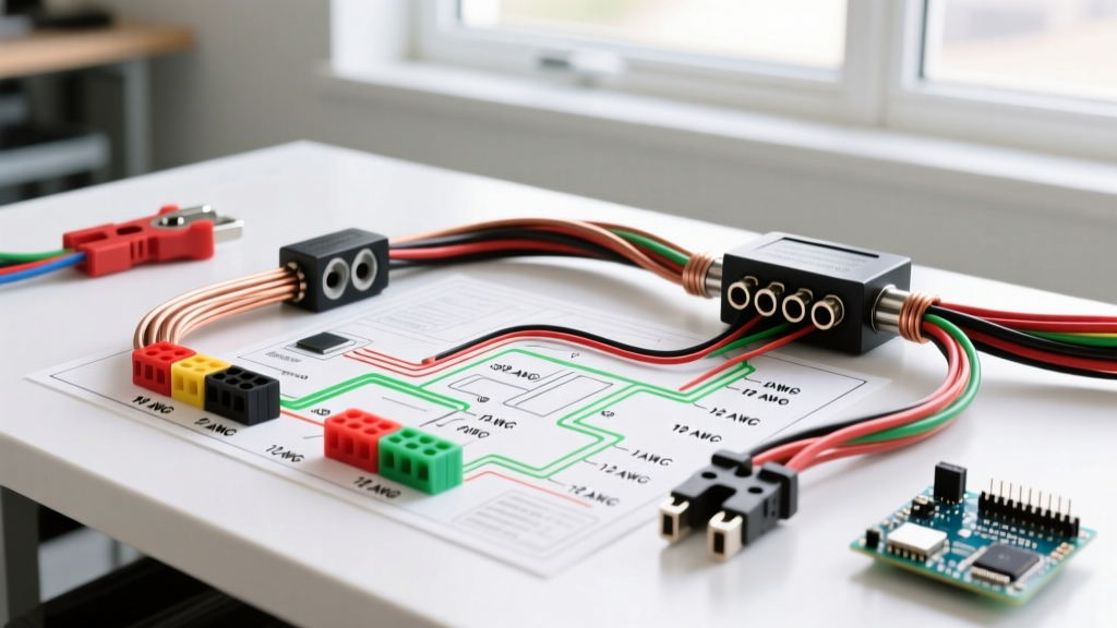
| Wire Connectors | Wago 221-412 (Lever) or Ideal Twister 341 | $0.35 / ea | Secure, vibration-resistant splices |
| Wall Box | Single-Gang Metal or PVC Old-Work | $2.50 | Thermostat housing |
Phase 1: Sizing the Branch Circuit and Breaker
A common misconception is that attic fans require massive dedicated circuits due to their physical size. In reality, a standard 1/4 HP, 120V attic fan draws approximately 3.2 to 4.5 Full Load Amps (FLA). Under NEC Article 430, a single motor on an individual branch circuit requires the branch-circuit short-circuit and ground-fault protective device to be sized appropriately, but a standard 15-Amp breaker on 14 AWG copper wire is more than sufficient for a dedicated fan run.
Expert Insight: If you plan to wire an attic light or a secondary ventilation device on the same run, upgrade to 12/2 NM-B cable and a 20-Amp single-pole breaker to accommodate future load additions without violating the 80% continuous load rule.
Always verify the motor's FLA on the manufacturer's data plate. If the fan includes an integrated heating element (rare for standard exhaust, but common in combo HVAC units), the amperage will dictate a much heavier gauge wire.
Phase 2: Routing the NM-B Cable
Running cable into an attic environment introduces extreme temperature variables. The U.S. Department of Energy notes that attic spaces can exceed 150°F (65°C) in the summer. Standard NM-B (Romex) cable is rated for 90°C (194°F), making it perfectly safe for attic routing, provided it is protected from physical damage.
- Drilling and Fishing: Drill a 3/4-inch hole through the top plate of the interior wall where the thermostat will reside. Fish the 14/2 NM-B cable from the main service panel to the thermostat location, leaving 8 inches of slack inside the single-gang wall box.
- Attic Run Protection: Route the cable from the thermostat box up into the attic. If the cable runs across floor joists within 6 feet of the attic scuttle hole or access point, NEC 334.23 requires it to be protected by running boards or conduit to prevent crushing by foot traffic.
- Securing the Cable: Staple the NM-B cable within 8 inches of the wall box and every 4.5 feet along the joists using insulated cable staples. Do not overtighten staples, as compressing the PVC jacket can alter the dielectric properties and damage the internal conductors.
Phase 3: Terminating the Line-Voltage Thermostat
The thermostat acts as the primary automated switch for your wiring diagram for attic fan operations. Line-voltage thermostats like the Honeywell CT410B break only the 'hot' leg of the circuit, meaning the neutral wire simply passes through to the fan motor.
Step-by-Step Termination
- Stripping the Jacket: Use a cable ripper to remove 10 inches of the outer PVC jacket. Strip exactly 11mm (7/16-inch) of insulation from the black, white, and bare copper wires if using Wago lever connectors, or 3/4-inch if using twist-on wire nuts.
- Neutral Pass-Through: Connect the incoming white (neutral) wire directly to the outgoing white wire heading to the attic fan. Use a Wago 221-412 connector. The thermostat does not interrupt the neutral path.
- Hot Leg Switching: Connect the incoming black (hot) wire from the panel to one of the thermostat's line terminals. Connect the outgoing black wire (heading to the fan) to the thermostat's load terminal. Note: Most line-voltage thermostats are non-polarized regarding line/load, but adhering to manufacturer labeling ensures proper internal thermal sensing.
- Grounding: Pigtail the incoming bare copper ground wire to the metal wall box (if applicable) and the thermostat's green ground screw using a 14 AWG bare copper pigtail and a green wire nut or lever connector.
Phase 4: Motor Junction Box Connections
At the attic fan housing, you will terminate the circuit into the motor's integrated junction box. This is where vibration and heat pose the greatest threat to wire integrity.
- Clamp and Secure: Feed the NM-B cable through a 1/2-inch NM cable connector (Romex clamp) screwed into the junction box knockout. Tighten the clamp screws until the cable is firmly seated and cannot be pulled out with moderate force.
- Wire Splicing: Connect the incoming black wire to the motor's black (or designated hot) wire. Connect the incoming white wire to the motor's white wire. Secure these with vibration-rated connectors. Wago 221 lever nuts are highly recommended here, as the constant vibration of a 1000+ RPM motor can gradually loosen traditional twist-on wire nuts over a 3-to-5-year period.
- Bonding: Connect the incoming ground wire to the motor junction box's green grounding screw and the motor's internal ground wire. Per UL Electrical Safety Guidelines, proper equipment grounding is non-negotiable to prevent the fan chassis from becoming energized in the event of an internal winding fault.
Advanced Configuration: Adding a Parallel Humidistat
In humid climates, temperature alone is an insufficient trigger for attic ventilation. Moisture buildup from winter ice dams or summer condensation can rot roof decking. To solve this, electricians wire a 120V humidistat in parallel with the thermostat.
The Parallel Wiring Logic:
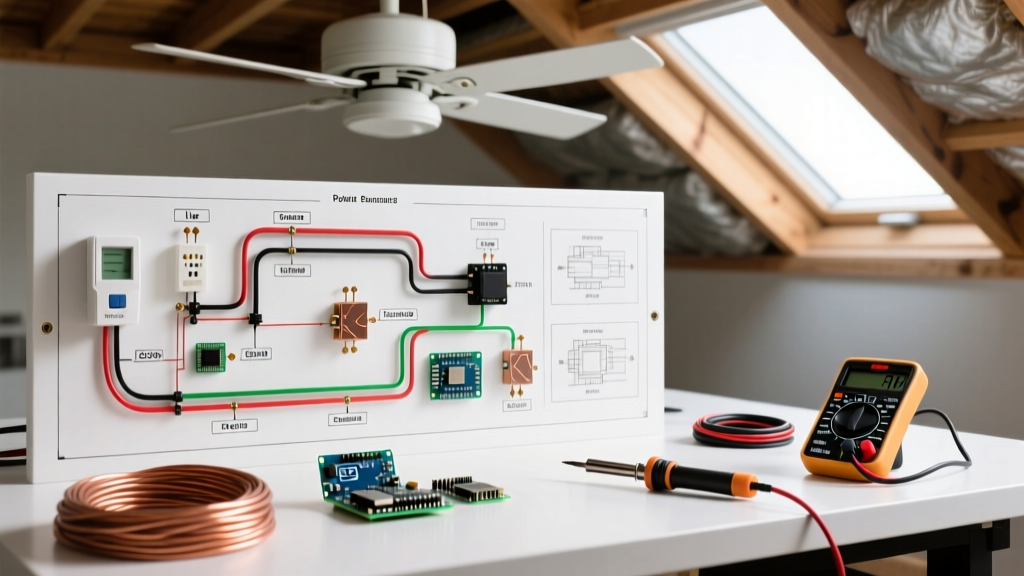
By wiring the hot leg through both the thermostat and the humidistat so that their load sides merge before entering the fan motor, you create an 'OR' logic gate. If the attic exceeds 95°F (thermostat triggers) OR if the relative humidity exceeds 60% (humidistat triggers), the circuit completes and the fan runs. To wire this, run a 14/3 NM-B cable from the thermostat box to the humidistat box, utilizing the red wire as the switched hot return from the humidistat, joining it with the black switched hot from the thermostat via a wire nut before continuing to the fan.
Troubleshooting Edge Cases and Failure Modes
Even with a perfect wiring diagram for attic fan execution, environmental factors can cause operational anomalies. Refer to this diagnostic matrix before assuming motor failure.
| Symptom | Probable Cause | Corrective Action |
|---|---|---|
| Fan short-cycles (turns on/off every 2 mins) | Thermostat placed too close to fan intake. | Relocate thermostat 10-15 feet away. The fan motor radiates heat; if the thermostat reads this exhaust heat, it shuts off prematurely. |
| Motor hums but impeller does not spin | Failed start/run capacitor or bound bearings. | Test the microfarad (µF) rating of the capacitor with a multimeter. Replace if reading is >10% below the printed spec. Lubricate bearings if applicable. |
| Breaker trips immediately upon engagement | Dead short or ground fault in NM-B run. | Check for staple punctures in the cable jacket. Verify no bare ground wires are touching the hot terminal screws inside the junction box. |
| Fan runs continuously, ignoring thermostat | Thermostat internal bimetallic strip is fused/welded. | Replace the line-voltage thermostat. High inductive loads from motor startups can pit and weld cheap internal contacts over time. |
Final Safety Verification
Before restoring power at the main service panel, perform a continuity and short-circuit test. Set your multimeter to the resistance (Ohms) setting. Place one probe on the hot bus bar terminal of the breaker and the other on the neutral bus bar. The reading should be infinite (OL). If you read near-zero resistance, you have a direct short that will cause an immediate arc-flash upon energizing. Once verified, install the breaker, restore power, and use a hair dryer to apply localized heat to the thermostat sensor to verify the switching mechanism engages the fan smoothly.