
The GMT400 Reality: Clarifying the 1997 "Silverado"
Before tracing a single circuit, it is crucial to understand the nomenclature of General Motors' truck lineup. When enthusiasts and mechanics search for a wiring diagram for 97 Chevy Silverado, they are technically looking for the schematics of the 1997 Chevrolet C/K 1500. In 1997, "Silverado" was not a standalone model; it was the top-tier trim package of the GMT400 platform. The actual Chevrolet Silverado model name did not replace the C/K designation until the 1999 model year (GMT800 platform). Therefore, the wiring architecture you are dealing with is the late-stage GMT400 harness, which features significant updates over the early 1988-1994 OBD-I systems, most notably the integration of the Vortec engine family and full OBD-II compliance.
Expert Note: As of 2026, these trucks are approaching 30 years old. The primary enemy of the GMT400 wiring harness is no longer just physical abrasion, but PVC insulation dry-rot and corrosion at the bulkhead connectors. Always inspect the firewall pass-through (C100/C200 connectors) for green copper oxide when diagnosing phantom electrical gremlins.
Decoding GM Schematics: Colors, Gauges, and Abbreviations
GM wiring diagrams utilize a highly standardized alphanumeric coding system. Unlike some European manufacturers that use complex numerical wire codes, GM relies on two-letter color abbreviations and circuit numbers. When reading a factory service manual (FSM) schematic, you will see a wire labeled something like 12 RD 14. This translates to: Circuit Number 12, Red wire, 14 AWG.
Standard GM Wire Color Abbreviations
| Abbreviation | Color | Common Application in '97 C/K 1500 |
|---|---|---|
| RD | Red | Battery positive, main power feeds, fusible links |
| BK | Black | Chassis ground, sensor ground returns |
| PK | Pink | Ignition-switched 12V (Run/Start circuits) |
| OG | Orange | Constant 12V battery feed (fused accessory) |
| GN | Green | High beam headlight feed, PCM sensor signals |
| TN | Tan | Low beam headlight feed, data lines |
| VT | Violet/Purple | Crankshaft position sensor, security system |
| YE | Yellow | Headlight switch to dimmer switch feed |
Critical Circuit Breakdown: Headlight and Dimmer Switch
The exterior lighting circuit on the 1997 GMT400 is a frequent point of failure due to the high current draw passing directly through the dashboard switches without the use of modern high-amperage relays for the main beams.
Step-by-Step Headlight Circuit Tracing
- Power Source: 12V power leaves the battery positive terminal through a 12 AWG Red fusible link wire. This is a critical failure point; if the truck has zero dash lights and no headlights, test for 12V at the headlight switch harness first.
- Headlight Switch: The main feed enters the headlight switch. When pulled to the first detent, power exits via a Brown (BN) wire to the tail lights and dash illumination. When pulled fully out, power exits via a Yellow (YE) 12 AWG wire.
- Multifunction (Dimmer) Switch: The Yellow wire travels up the steering column to the multifunction switch. The dimmer acts as a simple routing toggle.
- Beam Selection: If set to High, power routes to a Green (GN) wire. If set to Low, power routes to a Tan (TN) wire. Both are 12 AWG to handle the 65W+ halogen bulb draw.
2026 Upgrade Tip: Because the factory harness routes 15+ amps through a 29-year-old plastic switch, melting the headlight switch connector is incredibly common. If you find burnt pins, do not just replace the switch. Install an aftermarket headlight relay harness (e.g., Lisle or Painless Performance, typically $35-$50) that uses the factory Yellow wire only as a low-current trigger, pulling heavy current directly from the battery via 30A Bosch-style relays.
OBD-II DLC Pinout and Class 2 Serial Data
By 1997, all light-duty trucks were mandated to comply with OBD-II standards. The Data Link Connector (DLC) is located under the driver's side dash, near the hood release. While the physical 16-pin connector is universal, the internal pinout and communication protocols are GM-specific.
| Pin | Wire Color | Function / Protocol |
|---|---|---|
| 2 | Tan | GM Class 2 Serial Data (10.4 kbps) |
| 4 | Black/White | Chassis Ground |
| 5 | Black | Signal Ground (PCM reference) |
| 9 | Tan/White | Optional / Assembly Line Data |
| 12 | Purple | Tachometer Signal (from PCM) |
| 16 | Orange | Constant Battery Positive (12V) |
Diagnostic Insight: Modern bidirectional scanners (like the Autel MaxiSys or Snap-on Zeus) communicate with the 1997 Powertrain Control Module (PCM) via Pin 2 using GM's proprietary Class 2 Serial Data protocol. If your scanner powers on (Pin 16) but fails to link to the PCM, check the continuity of the Tan wire from the DLC back to PCM Connector C2, Pin 55. A broken Tan wire or a corroded splice (often labeled S2000 in the FSM) is the culprit in 80% of "No Comm" scenarios on late GMT400s.
Vortec L31 5.7L PCM and Sensor Wiring
The 1997 model year featured the legendary 5.7L Vortec (L31) engine. Unlike the older TBI (Throttle Body Injection) setups, the Vortec utilizes Sequential Multi-Port Fuel Injection (SFI), requiring a much more complex engine harness. The PCM uses three massive 80-way connectors (labeled C1, C2, and C3).
The Crankshaft Position Sensor (CKP) Edge Case
The CKP sensor on the 5.7L Vortec is a 2-wire magnetic pickup located on the passenger side of the engine block, near the bellhousing. The wires are Purple (VT) and Yellow (YE). Because this sensor operates on a low-voltage AC millivolt signal generated by the reluctor ring on the crankshaft, the wiring is highly shielded. A notorious failure mode on 1996-1998 Vortecs is the degradation of this shielding due to exhaust heat. When the insulation cracks, the CKP signal cross-talks with the high-voltage ignition coil wires. Symptom: The truck runs perfectly cold, but stalls abruptly when the engine bay reaches operating temperature, and will not restart until it cools down. Always test the CKP sensor with an oscilloscope, not just a multimeter, to verify the AC waveform integrity when hot.
Grounding Architecture and Common Failure Modes
GM's GMT400 platform relies heavily on localized grounding nodes. A poor ground will cause high-resistance voltage drops that mimic bad sensors or failing alternators. When using a wiring diagram to troubleshoot, always verify these primary ground nodes:
- G100: Left front corner of the engine compartment, near the battery. Grounds the main lighting harness and battery negative cable. Prone to rust where the eyelet meets the inner fender.
- G110: Left front cylinder head. Grounds the left bank fuel injectors and ignition coil. Must be clean, bare metal; paint or thread sealant will cause injector misfires.
- G111: Right front cylinder head. Grounds the right bank injectors and alternator field.
- G200: Right rear of the engine block, near the bellhousing. The main PCM power ground. If G200 is corroded, the PCM will lose its reference ground, causing erratic shifting, stalling, and false OBD-II codes (like P0122 or P0335).
Sourcing OEM Documentation and Standards
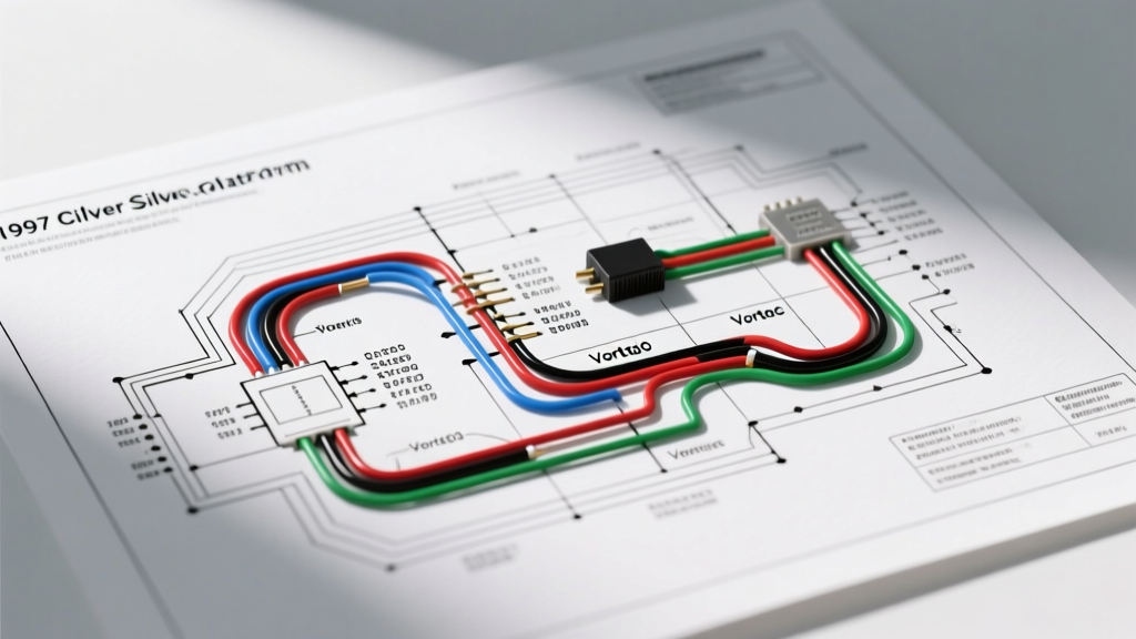
To perform advanced diagnostics, relying on internet forum screenshots is insufficient. You need the factory circuit numbers and splice locations. For authoritative data, reference the GM Heritage Center, which archives historical vehicle documentation and build specifications. For physical or digital copies of the original 1997 Truck Service Manuals, Helm Incorporated remains the official licensed publisher of GM service literature. Finally, for understanding the federal mandates and communication protocols governing the 1997 OBD-II systems, the National Highway Traffic Safety Administration (NHTSA) provides extensive regulatory archives on early emission control diagnostics and DLC standardization.
By combining the factory wiring diagram for 97 Chevy Silverado models with a modern understanding of PVC degradation and Class 2 data bus limitations, you can accurately diagnose and repair these iconic GMT400 trucks for decades to come.