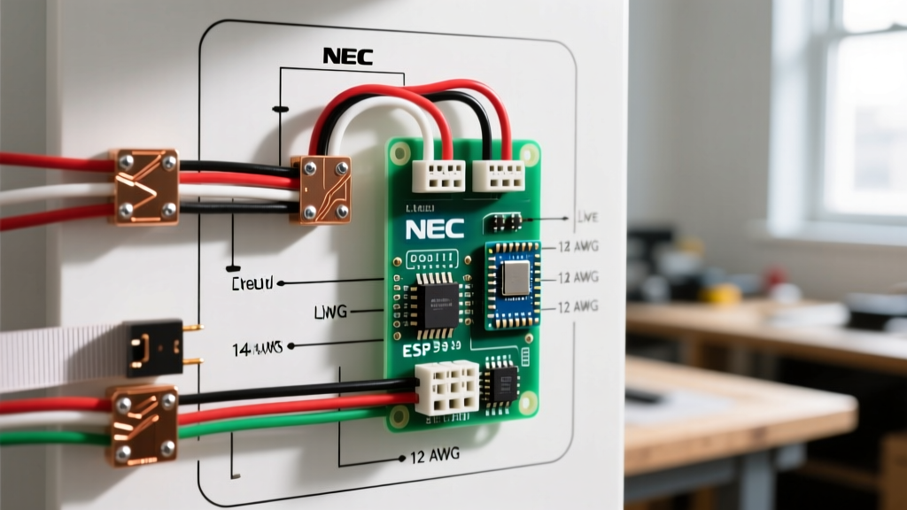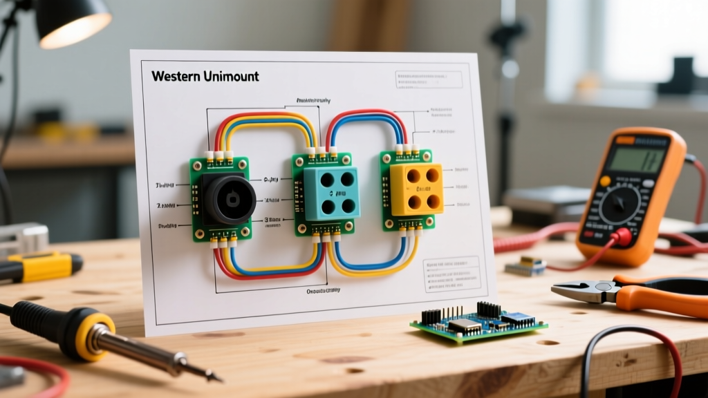

Introduction to Western Unimount Motor Wiring
Snowplow electrical systems operate in some of the harshest environments imaginable, demanding high current delivery under freezing, wet, and vibration-heavy conditions. The Western Unimount system remains one of the most reliable and widely deployed straight-blade plow mounts in North America. Whether you are retrofitting an older truck, replacing a burnt-out pump motor, or diagnosing a sluggish hydraulic lift, understanding the exact wiring diagram for Western Unimount plow configurations is critical.
In this comprehensive motor wiring tutorial, we will dissect the power delivery network, solenoid switching logic, and harness pinouts for both the legacy 2-plug and the standard 3-plug Unimount relay systems. We will also cover the transition from older Prestolite motors to modern Fenix permanent-magnet motors, providing actionable torque specs, wire gauge requirements, and advanced voltage-drop troubleshooting techniques.
Anatomy of the Unimount Pump Motor Circuit
Before tracing the wiring diagram, you must identify the specific generation of your motor and solenoid setup. Western has historically utilized two primary hydraulic pump motors on the Unimount platform:
- Prestolite EHY-516 (Legacy): A series-wound, field-coil motor. These are heavy, draw massive inrush currents (often exceeding 250 amps under load), and require robust 1/0 AWG cabling to prevent severe voltage drop.
- Fenix 56130 (Modern Standard): A permanent-magnet motor. Significantly lighter and more efficient, the Fenix draws approximately 150 amps under peak load. It is the direct replacement for the Prestolite and requires matching the solenoid duty cycle to the new amperage profile.
The motor does not connect directly to the cab controller. Instead, the cab controller triggers a low-current relay network, which in turn activates a high-current Trombetta intermittent-duty solenoid (typically part number 974-1215-011 or equivalent). This solenoid acts as the heavy-duty gatekeeper, bridging the vehicle's battery power to the plow's pump motor.
Decoding the Wiring Diagram for Western Unimount Plow Systems
The core power flow in a standard Unimount wiring diagram follows a strict, high-amperage path. Deviating from these wire gauges or routing paths will result in inadequate hydraulic pressure, causing the plow to drop or fail to angle under heavy snow loads.
The Main Power Feed (Battery to Solenoid)
According to the official Western Plows technical literature, the main power feed must originate directly from the vehicle's battery positive terminal or the main starter stud. Never route the plow's main power through the vehicle's under-hood fuse block, as the factory wiring is not rated for the 200+ amp draw of a snowplow motor.
- Wire Gauge: 2 AWG (minimum) or 1/0 AWG (recommended for cable runs exceeding 10 feet).
- Overcurrent Protection: A 175-amp or 200-amp mega-fuse or circuit breaker must be installed within 18 inches of the battery connection point.
The Control Trigger (Cab to Solenoid)
When the operator presses the 'Raise' or 'Angle' button on the in-cab controller, a low-amperage 12V signal is sent through the control harness to the isolation module or relay pack. This module then sends a 12V trigger signal to the small 'S' (Switch) terminal on the Trombetta solenoid. The solenoid coil energizes (drawing roughly 8 to 12 amps briefly), pulling the internal copper contactor down and bridging the main battery feed to the motor terminal.
2-Plug vs. 3-Plug Unimount Configurations
The physical harness connecting the truck to the plow dictates how the motor ground and control signals are managed. Below is a comparison matrix of the two primary Unimount harness styles:
| Feature | 2-Plug Unimount System | 3-Plug Unimount System |
|---|---|---|
| Plug 1 | 11-Pin Control & Lighting | 2-Pin Heavy Power (Battery + & Ground) |
| Plug 2 | 2-Pin Heavy Power (Motor Feed) | 11-Pin Control & Lighting |
| Plug 3 | N/A | 2-Pin Heavy Motor/Solenoid Feed |
| Motor Grounding | Grounded via chassis and Plug 1 | Dedicated heavy ground in Plug 1 |
| Best Application | Older trucks, simpler relay setups | Modern trucks, high-draw Fenix motors |
Expert Insight: If you are upgrading a 2-plug truck to a 3-plug plow (or vice versa), you must use a Western-approved adapter harness (e.g., Western Part # 29047 or # 29048). Attempting to manually splice a 2-plug control harness to a 3-plug power harness often results in melted control pins due to the proximity of high-amperage motor feedback.
Step-by-Step Motor & Solenoid Wiring Tutorial
When replacing the pump motor or solenoid on your Unimount setup, follow these exact termination and torque procedures to ensure winter reliability.
Step 1: Prep and Terminate the Heavy Cables
Strip the 2 AWG or 1/0 AWG battery cable using a dedicated wire stripper. Do not use a utility knife, as nicking the copper strands reduces the wire's cross-sectional area and creates a localized hot spot. Slide a piece of marine-grade, adhesive-lined heat shrink (3:1 shrink ratio) over the cable before crimping. Use a heavy-duty hex crimp tool—not a hammer or pliers—to compress the copper lug.
Step 2: Solenoid Mounting and Torque Specs
The Trombetta solenoid must be mounted to a clean, unpainted metal surface on the plow frame. The solenoid casing often serves as the ground path for the internal coil on older models (though newer 4-terminal models have a dedicated ground spade).
- Terminal Torque: Tighten the 5/16-inch stainless steel nuts on the main solenoid studs to exactly 12 to 15 ft-lbs. Over-torquing will strip the soft brass threads inside the solenoid; under-torquing will cause arcing and melt the plastic housing.
- Motor Stud Torque: The terminal nut on the top of the Fenix or Prestolite motor should be torqued to 8 to 10 ft-lbs.
Step 3: Apply Dielectric Protection
Once all connections are torqued, coat the exposed copper and terminal nuts generously with a high-quality dielectric grease (such as Permatex 22058 or NO-OX-ID A-Special). This prevents galvanic corrosion caused by road salt and brine, which is the number one cause of Unimount motor failure according to field technicians.
Advanced Troubleshooting: Voltage Drop & Load Testing
If your Unimount plow motor clicks but fails to turn, or turns sluggishly, do not immediately condemn the motor. As highlighted by the automotive electrical testing protocols at MAD Electrical, you must perform a voltage drop test under load to find the true culprit.
How to Perform a Motor Circuit Voltage Drop Test
- Prepare the Multimeter: Set your digital multimeter to DC Volts.
- Test the Positive Side: Place the red probe on the vehicle's battery positive post and the black probe on the motor's main power terminal. Have an assistant hold the 'Raise' button on the cab controller.
- Analyze Positive Drop: The multimeter should read less than 0.50V. If it reads 2.0V or higher, you have high resistance in the positive cable, the mega-fuse, or the internal contacts of the Trombetta solenoid.
- Test the Negative Side: Move the red probe to the motor casing (bare metal) and the black probe to the battery negative post. Engage the motor again.
- Analyze Negative Drop: The reading must be less than 0.20V. A higher reading indicates a poor ground connection at the motor mounting flange, the plow frame, or the vehicle chassis ground strap.
Common Failure Modes in Unimount Motor Wiring
- Solenoid Chatter (Rapid Clicking): This occurs when the control trigger wire suffers from voltage drop. The solenoid pulls in, but the voltage at the 'S' terminal drops below the holding threshold, causing it to release and re-engage rapidly. Check the 14 AWG red trigger wire for corrosion at the isolation module.
- Motor Spins but No Hydraulic Pressure: This is rarely an electrical issue. It usually indicates a sheared woodruff key on the motor shaft or a failed internal pump gear. However, verify that the motor is receiving a full 11.5V+ under load before tearing down the hydraulic reservoir.
- Melted 3-Plug Power Pins: If the large pins on your 3-plug harness show signs of melting or blackening, the plow ground wire is compromised. The motor is attempting to ground through the smaller control pins in the 11-pin connector, which instantly overloads and melts them.
Winterizing and Off-Season Storage Protocols
Proper off-season storage is vital for preserving the integrity of your Unimount wiring. When removing the plow for the summer:
- Disconnect the main battery feed at the vehicle's mega-fuse.
- Apply a liberal coat of fluid film or lanolin-based corrosion inhibitor to all exposed solenoid studs and motor terminals.
- Cap the 2-plug or 3-plug vehicle-side harnesses with OEM Western dust caps. If the caps are cracked or missing, replace them immediately; moisture ingress into the 11-pin control plug will short the lighting circuit and blow the cab controller's internal PCB traces.
- Store the plow motor side up or covered to prevent water from pooling around the top terminal nut, which can wick down into the motor windings and cause a dead short upon startup the following winter.
Frequently Asked Questions (FAQ)
Can I use a continuous-duty solenoid instead of the Trombetta intermittent solenoid?
No. Continuous-duty solenoids (like those used in winches or golf carts) have higher internal resistance and coil windings designed for long-term, low-heat operation. A snowplow motor requires an intermittent-duty solenoid capable of handling massive 250A+ inrush currents for short 5-to-15-second bursts. Using a continuous-duty solenoid will result in severe voltage drop across the solenoid contacts, starving the Unimount motor of amperage.
My wiring diagram shows a 4-terminal solenoid, but my truck has a 3-terminal. What do I do?
Older Unimount diagrams often feature a 3-terminal solenoid where the metal casing acts as the ground. Modern replacements are frequently 4-terminal, featuring an isolated ground spade. If you install a 4-terminal solenoid on a 3-terminal harness, you must run a dedicated 12 AWG ground wire from the new spade terminal directly to the plow frame. Failing to do so will result in a completely dead motor circuit.
What is the correct breaker size for a Fenix motor upgrade?
While the older Prestolite motors often utilized a 200-amp breaker due to their massive inrush current, the modern Fenix permanent-magnet motor is more efficient. Western Plows typically recommends a 175-amp circuit breaker for Fenix motor applications. Always verify the exact amperage rating printed on your specific Unimount relay module cover, as custom or fleet-modified setups may vary.