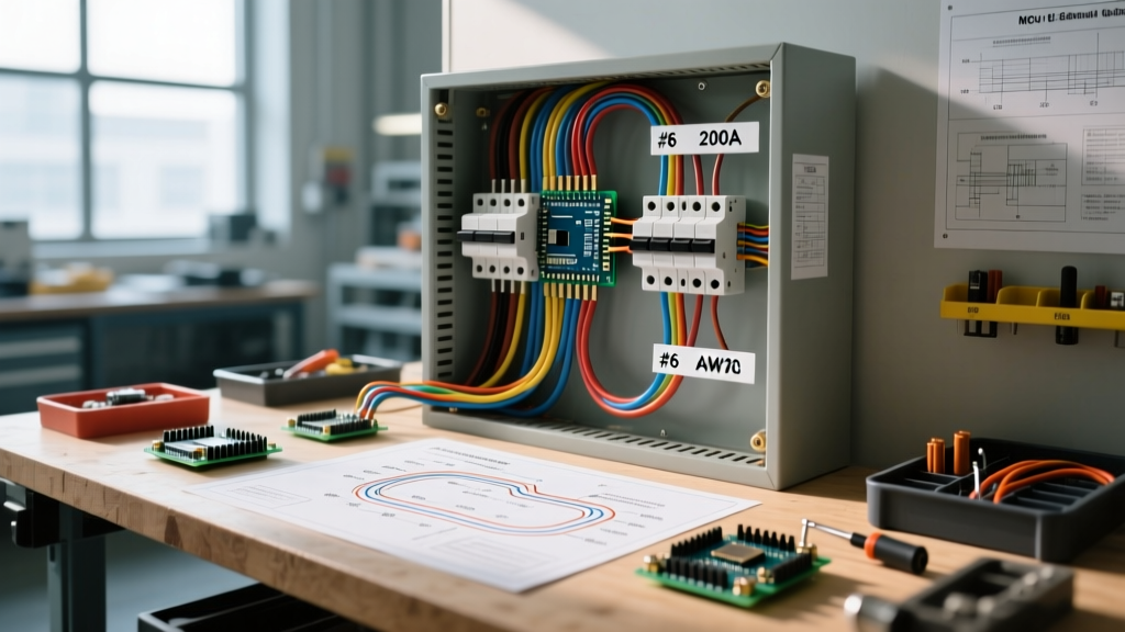

Introduction to Modern 200A Electrical Panel Wiring
As residential power demands surge in 2026 with the widespread adoption of Level 2 EV chargers, 60-amp heat pump circuits, and smart home ecosystems, the 200-amp main service panel has transitioned from a luxury to an absolute baseline. Proper electrical panel wiring is not merely about connecting wires; it is an exercise in thermal management, mechanical precision, and strict adherence to the National Electrical Code (NEC). This step-by-step walkthrough details the exact procedures for wiring a standard 200A residential main panel, specifically using the industry-standard Square D Homeline 200-Amp 40-Space Main Breaker Panel (Model: HOM40M200PC).
Safety Warning: Working inside a main service panel exposes you to lethal arc flash and shock hazards. The utility-side lugs remain energized even when the main breaker is OFF. Always follow OSHA Electrical Safety Guidelines and utilize proper Lockout/Tagout (LOTO) procedures before beginning any work.
Pre-Wiring Tooling and Material Matrix
Amateur electrical work often fails due to improper tooling. To meet NEC 110.14(D) requirements for calibrated torque, you must move beyond standard screwdrivers. Below is the mandatory tooling and material list for a compliant 200A installation.
- Panel Enclosure: Square D HOM40M200PC (Approx. $145 - $165 at major suppliers).
- Feeder Conductors: 2/0 AWG Copper THHN/THWN-2 or 4/0 AWG Aluminum XHHW-2.
- Torque Screwdriver: Klein Tools 63050 or Wiha 320P (Range: 10-70 in-lbs).
- Torque Wrench: For main lugs requiring higher ft-lb/in-lb values (e.g., 250-300 in-lbs).
- Wire Strippers: Klein Tools 11055 (for 10-18 AWG) and a heavy-duty cable stripper for 2/0 AWG.
- Voltage Tester: Milwaukee 48-22-4201 non-contact voltage tester and a CAT IV rated digital multimeter.
Conductor Sizing and Torque Specification Table
| Conductor Application | Material & Size (AWG) | NEC Reference | Target Torque |
|---|---|---|---|
| Main Service Hots (200A) | 2/0 Copper / 4/0 Aluminum | Article 310.12 | 250 - 300 in-lbs* |
| Main Neutral Conductor | 2/0 Copper / 4/0 Aluminum | Article 250.24 | 250 - 300 in-lbs* |
| Grounding Electrode (GEC) | 4 AWG Copper | Article 250.66 | 45 - 50 in-lbs* |
| Branch Circuit (15A/20A) | 14 AWG / 12 AWG Copper | Article 240.4 | 35 - 40 in-lbs* |
*Note: Always verify exact torque values printed on the panel's interior wiring diagram label, as manufacturer specifications supersede general guidelines.
Phase 1: Utility Disconnect and Verification
Before removing the panel cover, coordinate with your local utility provider to disconnect the meter or pull the meter socket. Once the utility confirms the drop is de-energized, use your CAT IV multimeter to test the incoming service conductors at the meter base. Only after verifying zero voltage should you proceed to mount the HOM40M200PC enclosure. Secure the enclosure to the studs using minimum 1/4-inch lag screws, ensuring the centerline of the panel is positioned between 48 and 60 inches from the finished floor to meet NEC 240.24 accessibility requirements.
Phase 2: Feeder Cable Routing and Main Termination
Pulling 2/0 AWG copper or 4/0 AWG aluminum into a residential panel requires careful bending radius management to avoid stressing the termination lugs.
- Prepare the Conductors: Strip exactly 1-1/4 inches of insulation from the feeder conductors. Do not nick the copper or aluminum strands, as this creates a localized hot spot under load.
- Route the Hots: Feed the two ungrounded (hot) conductors through the top knockouts. Route them down the side wire gutters, maintaining a clean, sweeping bend into the main breaker lugs.
- Terminate the Neutral: Route the grounded (neutral) conductor to the main neutral bar. In a main service panel, the neutral bar must be bonded to the enclosure via the green bonding screw or bonding strap provided with the panel.
- Apply Calibrated Torque: Using your torque wrench, tighten the main lugs to the manufacturer's specified value (typically 250-300 in-lbs). According to the National Fire Protection Association (NFPA), failure to use a calibrated torque tool is a leading cause of thermal failures in modern high-load panels.
Phase 3: Grounding Electrode System (GES) Integration
The Electrical Safety Foundation International (ESFI) emphasizes that a properly wired panel is useless without a robust grounding path. For a 200A service, NEC 250.66 requires a minimum 4 AWG bare copper Grounding Electrode Conductor (GEC).
- Route the 4 AWG GEC from the panel's ground bar to the exterior grounding electrode (typically two 5/8-inch x 8-foot copper ground rods driven 6 feet apart, or a Ufer ground).
- Terminate the GEC at the panel's ground bar using a torque screwdriver set to 45 in-lbs.
- Critical Distinction: In this main service panel, the ground bar and neutral bar are bonded. However, ensure that no equipment grounding conductors (EGCs) from branch circuits are terminated on the neutral bar. All branch grounds must land on the dedicated ground bar to prevent neutral current from traveling on grounding paths.
Phase 4: Branch Circuit Wiring Walkthrough
With the main feed secured, the focus shifts to branch circuits. Modern electrical panel wiring demands strict adherence to AFCI (Arc-Fault Circuit Interrupter) and GFCI (Ground-Fault Circuit Interrupter) mandates outlined in NEC 210.8 and 210.12.
Standard 120V Circuit Termination
- Sheath Removal: Strip the outer NM-B jacket exactly at the panel knockout. NEC 300.11 requires the sheath to enter the enclosure by at least 1/4 inch.
- Neutral Routing: Route the white neutral wire directly to the neutral bar. Do not coil excess wire tightly; use sweeping loops to allow for future thermal expansion.
- Ground Routing: Terminate the bare copper ground to the ground bar. Torque to 35 in-lbs.
- Hot Termination: Insert the black hot wire into the breaker terminal (e.g., Square D HOM120 20A). Torque the breaker terminal screw to 40 in-lbs. Snap the breaker firmly into the bus bar stab.
240V Appliance Circuit Walkthrough (e.g., EV Charger or Range)
For a 60A Level 2 EV charger, you will utilize a 60A double-pole breaker (HOM260) and 6 AWG copper THHN in a conduit, or 6/2 NM-B if permitted by local amendments.
- Connect the two hot legs to the double-pole breaker.
- If the appliance requires a neutral (like a range), terminate the white wire on the neutral bar.
- Terminate the equipment ground on the ground bar.
- Ensure the breaker's handle tie is intact to guarantee simultaneous disconnect of both ungrounded conductors.
Edge Cases and Common Failure Modes
Even experienced DIYers make critical errors during electrical panel wiring. Avoid these specific failure modes:
- Double-Tapped Neutrals: NEC 408.41 strictly prohibits terminating more than one neutral conductor under a single neutral bar screw. This causes uneven current distribution and can overload the screw terminal, leading to arcing.
- Over-Torquing Aluminum Feeders: If using 4/0 Aluminum XHHW-2, over-tightening the main lugs will strip the soft aluminum threads or cause the conductor to cold-flow, resulting in a loose connection months later. Always use a calibrated torque wrench.
- Missing Bonding Strap: Failing to install the green bonding screw or strap in a main
- Pigtail Overcrowding: While wire nuts inside the panel are permitted for pigtailing, excessive splicing in the side gutters restricts airflow and violates NEC 312.8 regarding wire space capacity. Run continuous conductors from the load to the breaker whenever possible.
Final Inspection and Energization
Before calling for the municipal rough-in or final inspection, perform a self-audit. Verify that every breaker is labeled accurately using the panel's directory card. Ensure no bare copper is exposed outside of terminal connections. Once the inspector signs off, coordinate with the utility to reinstall the meter. Stand to the side of the panel, wear safety glasses, and firmly throw the main breaker to the ON position. Follow up by testing every branch circuit with a receptacle tester to confirm correct polarity and grounding continuity. Mastering electrical panel wiring requires patience, precision tooling, and an unwavering respect for the physics of high-amperage electricity.