
The Architecture of Safe Towing: Planning Your Trailer Brake Installation
Wiring electric trailer brakes is not merely about connecting copper to terminals; it is about engineering a fail-safe deceleration system that operates reliably under high-amperage loads and harsh environmental conditions. Whether you are outfitting a 2026 overland camper or rewiring a vintage car hauler, understanding the wiring diagram for trailer brakes is the foundational step in preventing voltage drop, brake lockup, and catastrophic hitch failures.
This installation planning guide moves beyond generic color-code charts. We will dissect the 7-way RV blade connector standard, calculate precise wire gauge requirements based on amperage and distance, and integrate the critical breakaway safety circuit. By the end of this guide, you will have a complete, actionable blueprint for your trailer brake installation.
⚠️ Safety & Compliance Notice: Electric trailer brake systems must comply with both state towing laws and federal regulations. According to FMCSA 49 CFR § 393.43, any trailer equipped with a breakaway brake system must have a mechanism capable of holding the brakes in the applied position for a minimum of 15 minutes after a complete disconnect from the tow vehicle.
Phase 1: Component Selection & Sizing (2026 Market Data)
Before cutting a single length of wire, you must select components matched to your trailer's Gross Vehicle Weight Rating (GVWR). Undersized brake controllers or sub-standard wiring will result in delayed braking response and overheated circuits.
1. Brake Controller Selection
Modern proportional brake controllers use internal accelerometers to match the tow vehicle's deceleration rate. As of 2026, the market leaders remain highly competitive:
- Tekonsha Prodigy P3 (Model 90195): Retailing around $165, this remains the gold standard for heavy-duty towing. Its boost feature allows you to pre-load the trailer brakes to 25% output when starting on steep downgrades.
- Curt Spectrum (Model 51175): Priced near $215, this unit features a highly sensitive tri-axis accelerometer and an intuitive knob interface, ideal for frequent towers switching between multiple trailers.
2. Wire Gauge Sizing Matrix
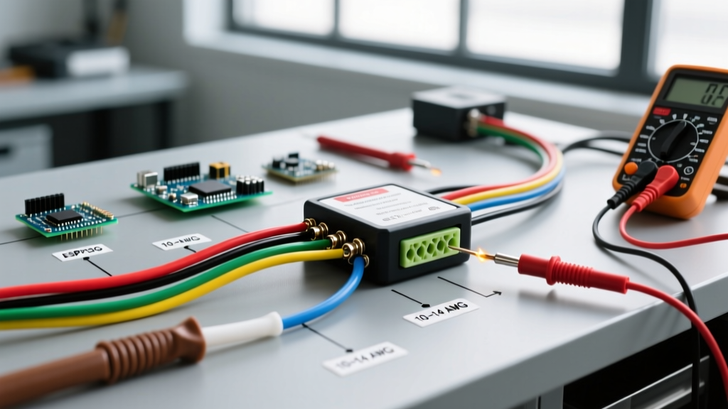
The most common failure in trailer brake wiring is excessive voltage drop caused by undersized conductors. Electric trailer brakes typically draw between 3.0 to 4.5 amps per wheel under maximum load. A dual-axle trailer (4 wheels) can pull up to 18 amps continuously during an emergency stop. The ground wire must be equal to or larger than the power wire to complete the circuit efficiently.
| Trailer Length (Tongue to Axle) | Brake Power Wire (AWG) | Ground Return Wire (AWG) | 12V Aux Charge Line (AWG) |
|---|---|---|---|
| Under 15 Feet | 12 AWG | 10 AWG | 10 AWG |
| 15 to 25 Feet | 10 AWG | 8 AWG | 8 AWG |
| 25 to 35 Feet | 8 AWG | 6 AWG | 6 AWG |
| Over 35 Feet (Gooseneck/5th Wheel) | 6 AWG | 4 AWG | 6 AWG |
Phase 2: Decoding the 7-Way Wiring Diagram for Trailer Brakes
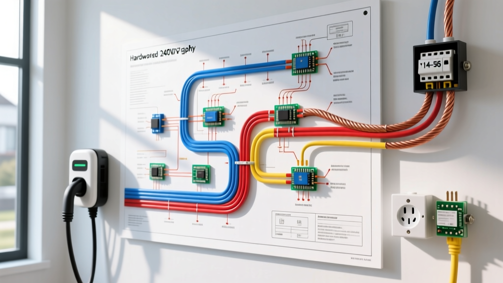
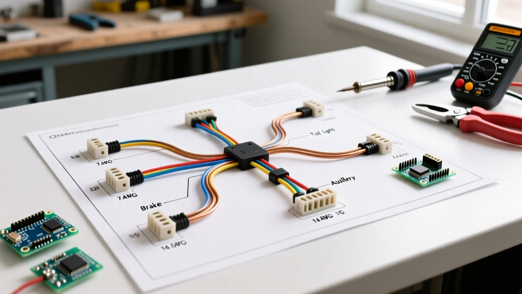
The 7-way RV blade connector (SAE J2862 / RVIA standard) is the universal interface for electric brakes. For a comprehensive visual pinout verification, you can cross-reference the etrailer wiring FAQ database, but here is the exact functional breakdown you need for your installation plan.
The RVIA Standard 7-Way Pinout (Trailer Side)
When looking at the trailer-side plug with the hinged lid facing up and the prongs facing you, the pinout is as follows:
- Pin 1 (White) - Ground Return: This is the master ground for the entire trailer. It must be terminated to the trailer frame using a star washer and bare metal. Do not ground through the hitch ball.
- Pin 2 (Blue) - Electric Brakes: Carries the modulated DC voltage (0-12V) from the tow vehicle's brake controller directly to the brake magnets.
- Pin 3 (Green) - Tail/Running Lights: 12V constant when headlights are on.
- Pin 4 (Black) - 12V Auxiliary Power: Constant 12V from the tow vehicle's battery. This powers interior lights, winches, and crucially, the breakaway switch.
- Pin 5 (Red) - Left Turn/Stop: 12V pulsing/constant for left side markers and brake lights.
- Pin 6 (Brown) - Right Turn/Stop: 12V pulsing/constant for right side markers and brake lights.
- Pin 7 (Yellow) - Reverse Lights/Backup Lamps: 12V when the tow vehicle is in reverse.
Pro-Tip: The 'Hitch Ball Ground' Fallacy
Novice installers often rely on the physical coupling between the trailer tongue and the hitch ball for their main ground return. This is a critical failure point. Rust, paint, and grease act as dielectrics, causing high resistance. This manifests as dim running lights, erratic brake controller behavior, and the infamous 'brakes lock up when headlights turn on' symptom. Always run a dedicated, heavy-gauge white ground wire directly to the trailer frame.
Phase 3: Breakaway Switch Integration & Logic
The breakaway switch is your last line of defense if the trailer detaches from the hitch. It consists of a pin-and-lanyard mechanism wired to a dedicated 12V battery on the trailer. When the lanyard pulls the pin, the switch closes, sending full battery voltage to the brake magnets.
Wiring the Breakaway Switch Correctly
A common and dangerous mistake is wiring the breakaway switch to the blue brake output wire (Pin 2). If wired this way, the breakaway system will attempt to pull power backward through the tow vehicle's brake controller, potentially destroying the controller's internal circuitry and failing to stop the trailer.
The Correct Circuit Path:
- Positive Terminal (Red Wire): Connect directly to the positive terminal of the trailer-mounted breakaway battery (typically a 12V, 5Ah sealed lead-acid or AGM battery).
- Switch Output (Black Wire): Splice directly into the Blue (Pin 2) brake power wire, downstream of the 7-way plug but upstream of the brake magnets.
- Battery Ground (White Wire): Connect to the trailer frame.
- Battery Charging: Run a dedicated 10 AWG wire from the Black (Pin 4) 12V Aux pin on the 7-way plug to the positive terminal of the breakaway battery, passing through a 20-amp inline circuit breaker and a 12V diode (to prevent the breakaway battery from back-feeding into the tow vehicle's electrical system).
Phase 4: Routing, Termination, and Weatherproofing
The environment beneath a trailer is hostile, subjected to road salt, debris impacts, and constant vibration. Standard vinyl electrical tape will degrade and unravel within a single season. Plan your routing with the following materials and techniques:
- Conduit Protection: Route all main harness wires through split loom tubing (1/2 inch diameter) or flexible nylon braided sleeving. Secure the conduit every 18 inches using UV-resistant zip ties or rubber-cushioned Adel clamps (P-clips) bolted to the frame.
- Termination Hardware: Abandon cheap ring terminals. Use adhesive-lined, dual-wall heat shrink terminals (e.g., 3M FP-301). When crimped and heated, the inner adhesive melts and seals the wire strands, preventing capillary action from drawing moisture into the copper.
- Connector Sealing: Pack the 7-way plug housing and all brake magnet wire nuts with a high-quality dielectric grease (such as Permatex 22058). This displaces moisture and prevents galvanic corrosion between dissimilar metals (e.g., copper wire and steel brake magnet leads).
- Magnet Wire Routing: The flexible wires leading from the axle to the brake backing plate are highly susceptible to snagging. Route them through the axle's internal tubing if possible, or use heavy-duty rubber grommets where the wire passes through the backing plate to prevent the sharp steel edge from slicing the insulation.
Troubleshooting Matrix: Common Installation Failures
Even with a meticulous plan, electrical gremlins can emerge during the final voltage testing phase. Use this matrix to diagnose anomalies before taking the rig to the highway.
| Symptom | Probable Cause | Diagnostic Action & Fix |
|---|---|---|
| Brakes lock up or engage when headlights are turned on. | Cross-wired pins at the 7-way plug, or a shared/weak ground causing current to back-feed through the lighting circuit. | Verify Pin 1 (Ground) and Pin 2 (Brakes) are not shorted. Ensure dedicated ground wire is bonded to bare frame metal. |
| Brake controller displays 'OL' (Overload) or 'SH' (Short) immediately upon connection. | The blue brake wire is pinched against the frame, or a brake magnet internal coil has shorted to the backing plate. | Disconnect magnets one by one. Use a multimeter to check resistance across the blue wire and ground. A dead short (0 ohms) indicates a pinched wire or blown magnet. |
| Brakes feel weak; controller maxes out at 10.0 but deceleration is poor. | Severe voltage drop due to undersized wiring, or corroded plug pins reducing amperage delivery. | Measure voltage at the brake controller output, then measure at the trailer axle. A drop greater than 1.5V under load indicates the need for heavier gauge wire or contact cleaning. |
| Breakaway switch fails to engage brakes when pin is pulled. | Inline fuse blown, breakaway battery dead, or switch wired to the brake controller output instead of the battery. | Test breakaway battery voltage (must be >12.4V). Verify continuity through the switch when the pin is removed. |
Final Verification Protocol
Before loading the trailer, elevate the wheels off the ground using jack stands. Have an assistant sit in the tow vehicle with the engine running and the manual override lever on the brake controller fully engaged. Spin each wheel by hand. You should feel significant, smooth resistance without any metallic grinding or pulsating. Finally, pull the breakaway lanyard and verify that all wheels lock completely. Adhering strictly to this wiring diagram for trailer brakes and installation plan ensures your rig is not only legally compliant but engineered for absolute safety on the road.