
Understanding the GY6 Electric Choke Circuit
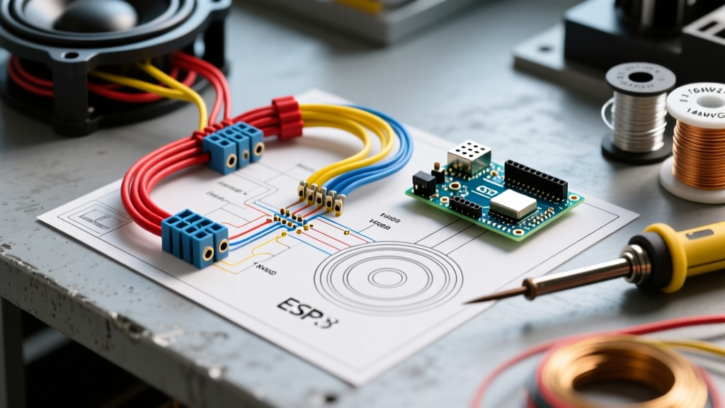
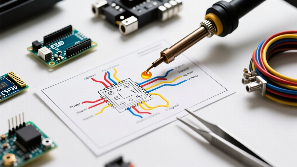
The GY6 engine family—most notably the 139QMB (50cc) and 157QMJ (150cc) powerplants—remains the backbone of the global scooter, ATV, and go-kart market. While 2026 has seen a rise in aftermarket EFI (Electronic Fuel Injection) kits, the vast majority of GY6 engines on the road still rely on traditional carburetors equipped with an automatic bystarter, commonly known as an electric choke. Understanding the GY6 electric choke wiring diagram is critical for diagnosing cold-start issues, rich-running conditions, and stalling at idle.
Unlike automotive chokes that may rely on coolant temperature sensors or 12V DC battery power, the standard GY6 electric choke is designed to operate on 12V AC (Alternating Current) generated directly by the stator's lighting coil. This is a fundamental design choice: the choke only receives power when the engine is actually running and generating electricity, preventing battery drain if the ignition key is left in the 'ON' position without the engine cranking.
Wire Gauge Selection for the Choke Circuit
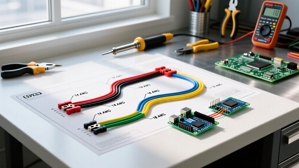
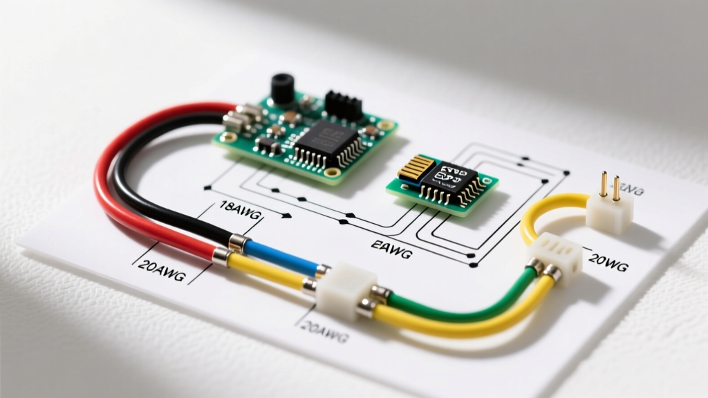
Selecting the correct wire gauge for your choke circuit is essential for safety and reliability. The heating element inside a standard GY6 automatic bystarter typically draws between 1.5 to 2.5 Amps of current.
- 18 AWG Wire: According to standard AWG wiring specifications, 18 AWG copper wire is rated for up to 14 Amps in chassis wiring applications. This is more than sufficient for the 2.5A draw of the choke heater.
- 16 AWG Wire (Recommended): While 18 AWG handles the electrical load easily, small engines generate significant high-frequency vibration. Upgrading to 16 AWG stranded copper wire provides superior mechanical durability, reducing the risk of internal wire strand fatigue and breakage over time.
Pro Tip: Always use high-quality, multi-strand copper wire with a PVC or cross-linked polyethylene (XLPE) jacket rated for at least 105°C (221°F), as engine bay temperatures near the carburetor can easily exceed 80°C during summer operation.
Standard GY6 Harness Color Code Reference
Chinese-manufactured GY6 wiring harnesses generally follow a standardized color code, though variations exist between specific OEM assemblers. Below is the definitive color code reference for the stator, regulator/rectifier, and choke circuit.
| Wire Color | Function | Destination / Notes |
|---|---|---|
| Yellow | 12V AC Power (Lighting/Choke) | Stator to Regulator/Rectifier & Choke Heater |
| Green | Ground (Earth) | Choke Ground, Frame Ground, Battery Negative |
| White | 12V AC Power (Charging) | Stator to Regulator/Rectifier (Battery Charging) |
| Pink / Black-Red | Ignition Coil Power | CDI to Ignition Coil |
| Black-White | Kill Switch / Ground Out | CDI to Ignition Switch (Grounds to kill engine) |
Step-by-Step Wiring & Connection Guide
When replacing a faulty choke or repairing a damaged harness, follow this precise wiring sequence to ensure proper operation:
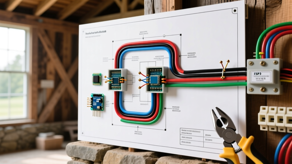
- Locate the Stator Yellow Wire: Trace the yellow wire from the stator output (usually a 4-pin or 6-pin connector near the CVT cover). Tap into this wire using a proper solder-and-heat-shrink method. Avoid 'scotch-lock' tap connectors, which corrode quickly in outdoor environments.
- Route the Power Wire: Run an 18 AWG or 16 AWG yellow wire from your tap point to the choke connector. Ensure the wire is routed away from the exhaust header and the CVT belt intake.
- Establish the Ground: Connect the second choke wire (usually green) to a clean, bare-metal point on the engine block or carburetor mounting flange. Use a ring terminal and a star washer to bite through any paint or powder coating, ensuring a solid electrical bond in accordance with NFPA 70 grounding principles.
- Secure the Connector: The choke itself uses a standard 2-pin waterproof connector. Apply a small amount of dielectric grease to the pins before mating to prevent moisture ingress.
Diagnostic Testing: Multimeter & Resistance Values
Before replacing a suspect choke, verify its internal health using a digital multimeter. As outlined in Fluke's electrical testing guidelines, measuring resistance is the most reliable way to test heating elements.
1. Cold Resistance Test (Ohms)
Disconnect the choke from the harness. Set your multimeter to the Ohms (Ω) setting, typically the 200Ω range. Place the probes on the two pins of the choke connector. A healthy GY6 choke will read between 5.0 Ω and 12.0 Ω. If the meter reads 'OL' (Open Loop) or infinite resistance, the internal heating wire is broken, and the choke must be replaced.
2. Live Voltage Test (AC Volts)
Reconnect the choke. Set the multimeter to AC Voltage (V~). Back-probe the connector while the engine is running at idle. You should read between 11V AC and 14V AC. If you read 0V, your stator lighting coil or the yellow wire tap is faulty.
3. Plunger Extension Test (Physical)
The choke operates by heating a wax pellet or bimetallic spring, which pushes a brass plunger outward to close the enrichment circuit.
Cold State: The plunger should be retracted (approx. 28mm from base to tip).
Hot State: After 3 to 5 minutes of running the engine (or applying 12V AC directly for testing), the plunger should fully extend to approximately 38mm. If it does not extend, the enrichment circuit remains open, causing the engine to run rich, foul the spark plug, and emit black smoke.
⚠️ Critical Warning: The DC Wiring Mistake
A massive percentage of DIY choke failures stem from wiring the yellow choke wire to a 12V DC source (like the battery or the red ignition switch wire). If wired to DC, the choke will activate whenever the key is turned on, even if the engine isn't running. This will drain your battery in hours and can overheat the choke element, melting the internal plastic housing and destroying the unit.
Common Failure Modes & Edge Cases
Even with correct wiring, GY6 chokes are subject to specific failure modes inherent to their design and operating environment:
- Melted Bullet Connectors: The 2-pin connector is often located near the engine block. If the rubber boot is missing, water intrusion causes corrosion, increasing resistance. This localized resistance generates excess heat, melting the plastic connector housing. Fix: Cut off the melted connector and solder a new, sealed 2-pin Deutsch or OEM-style connector.
- Wax Pellet Leakage: Inside the choke is a volatile wax compound. If the choke is subjected to extreme physical impact or manufacturing defects, the wax can leak out. The choke will heat up, but the plunger will not extend. This requires complete replacement.
- Aftermarket Choke Quality Variance: As of 2026, standard aftermarket GY6 chokes cost between $8 and $15, while genuine OEM or Japanese-equivalent (Keihin) units cost $35 to $55. The cheaper units often use inferior PTC thermistors that degrade after 6-12 months, leading to intermittent cold-start failures. Investing in the OEM unit is highly recommended for daily riders.
The Manual Choke Conversion Alternative
For off-road applications, go-karts, or riders in extremely cold climates where the automatic choke fails to provide enough enrichment, converting to a manual cable choke is a popular edge-case modification. This involves removing the electric bystarter, installing a manual choke plunger kit (approx. $12), and routing a Bowden cable to the dashboard. While it sacrifices the 'turn-key' convenience, it provides 100% mechanical reliability and eliminates the electrical wiring harness entirely, a preferred setup for dedicated racing or heavy-duty utility applications.
Summary
Mastering the GY6 electric choke wiring diagram requires understanding the distinction between AC stator power and DC battery power. By adhering to the standard yellow (AC power) and green (ground) color codes, utilizing 16 AWG or 18 AWG stranded wire, and verifying resistance values between 5 and 12 ohms, you can ensure reliable cold starts and optimal fuel efficiency for your 50cc or 150cc scooter.