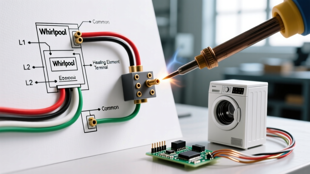

Understanding the 240V Whirlpool Dryer Heating Circuit
Diagnosing a no-heat condition in a Whirlpool electric dryer requires more than just swapping parts; it demands a thorough understanding of the underlying electrical architecture. The wiring diagram for a Whirlpool dryer heating element outlines a 240-volt resistive circuit integrated with multiple thermal safety devices and a unique motor interlock. Whether you are working on a legacy Whirlpool LER series, a Cabrio top-load matching dryer, or a modern Duet front-load pair, the fundamental principles of the heating circuit remain consistent.
Electric dryers in North America operate on a split-phase 240V supply. This means the heating element does not utilize the neutral wire. Instead, it relies on both 'hot' legs (L1 and L2) to create the 240V potential required to generate 5,000+ watts of heat. If your dryer tumbles but produces zero heat, the issue is almost always localized to the L1/L2 heating circuit, the thermal fuses, or the element itself.
The Motor Centrifugal Switch Interlock
One of the most critical, yet frequently misunderstood, aspects of the Whirlpool heating element wiring diagram is the motor centrifugal switch. The L1 hot leg is routed through a centrifugal switch located on the drive motor before it ever reaches the heating element coil. This is a deliberate fire-prevention engineering control. If the blower motor fails to spin, air cannot move through the heater box. By wiring the heater in series with the motor's centrifugal switch, the dryer guarantees that the heating element can only energize when the blower is actively exhausting air, preventing catastrophic overheating and potential structural fires.
Terminal Block Pinout and Power Delivery
Before tracing the internal wiring, you must verify the power delivery at the terminal block. Modern installations require a 4-prong NEMA 14-30 receptacle, though older homes may still use 3-prong NEMA 10-30 configurations.
- Left Terminal (L1): Red wire (10 AWG). Carries 120V to the motor switch and heater.
- Center Terminal (N): White wire (10 AWG). Neutral for the 120V motor, timer, and control board. The heater does not use this wire.
- Right Terminal (L2): Black wire (10 AWG). Carries 120V to the thermostats and back to the heater.
- Chassis Ground: Green or bare copper wire bonded directly to the dryer frame.
Expert Warning: A loose neutral wire on the terminal block will allow the 240V heater to function, but the 120V control board and motor will fail to operate. Conversely, a loose L1 or L2 wire will result in the motor running (if it can find a return path or if only one leg is dropped at the breaker) but zero heat at the element. Always torque terminal block screws to 12-15 inch-pounds.
Step-by-Step Circuit Trace: From Breaker to Coil
To effectively use the wiring diagram for a Whirlpool dryer heating element, trace the current path sequentially. A break anywhere in this series circuit will result in a cold dryer.
- L1 Ingress: 120V enters via the red wire at the terminal block.
- Centrifugal Switch: Current travels to the motor switch (pins 1 and 2). It only passes through when the motor reaches operating RPM.
- Heating Element Coil: Current enters one terminal of the heater assembly, passing through the nichrome wire coils suspended in ceramic insulators.
- Thermal Cutoff (High-Limit): Exiting the heater box, the current passes through the thermal cutoff (a one-time-use fusible link designed to melt at 290°F / 143°C).
- High-Limit Thermostat: Next in line is the cycling high-limit thermostat, which opens at 250°F to prevent duct fires if the vent is partially restricted.
- Cycling Thermostat / Thermistor: The circuit routes to the operating thermostat (or electronic thermistor on newer models), which regulates the internal drum temperature based on the user's fabric selection.
- Timer or Electronic Control Board (CCU): Finally, the current passes through the timer contacts (on mechanical models) or a Solid State Relay / Triac (on digital models) before returning to the L2 black wire at the terminal block.
Component Diagnostics & Exact Part Numbers
When testing with a digital multimeter, set your dial to Ohms (Ω) and ensure the dryer is completely disconnected from the 240V power supply. Below is a reference matrix for standard Whirlpool electric dryer heating components.
| Component | Common Whirlpool Part # | Expected Multimeter Reading | Primary Failure Symptom |
|---|---|---|---|
| Heating Element Assembly | WP3387747 / 279838 / WP8544771 | 10 Ω to 50 Ω | No heat, or breaker instantly trips (if shorted to ground) |
| Thermal Cutoff Kit | WP3392519 / 279816 | 0 Ω (Continuity) | No heat; element receives zero voltage |
| High-Limit Thermostat | WP3390719 | 0 Ω (Continuity) | No heat; often blows due to blocked exhaust vent |
| Cycling Thermostat | WP3387134 | 0 Ω (Continuity) | Dryer overheats, shuts off prematurely, or won't heat |
| Thermal Fuse (Exhaust) | WP3392519 | 0 Ω (Continuity) | Dryer will not start or tumble at all (breaks main 120V motor circuit) |
Modern 2026 Architectures: Electronic Control Boards and Triacs
While older Whirlpool models routed L2 through a mechanical timer, modern Whirlpool dryers (including recent Cabrio and Duet variants) utilize an Electronic Control Board. In these wiring diagrams, the mechanical timer contacts are replaced by a Triac or Solid-State Relay (SSR) mounted on the main control board.
When the control board receives the signal from the thermistor that the drum temperature is below the target setting, it triggers the gate on the Triac, allowing L2 current to flow through the heating element. If your heating element tests perfectly (approx. 15 Ω), and all thermal fuses show continuity, but the heater still receives no voltage, the fault often lies in a failed Triac on the control board or a broken wire in the harness connecting the CCU (Central Control Unit) to the heater circuit. Always inspect the wire harness pins for 'pin push-out' or micro-corrosion before condemning the control board.
Step-by-Step Replacement Tutorial
Replacing the heating element requires careful handling of the ceramic insulators and spade connectors. Follow this procedure to ensure a safe, lasting repair.
1. Accessing the Heater Box
On most Whirlpool front-load (Duet) models, you must remove the lower front kick panel (usually secured by three 1/4-inch hex screws). The heater box is located on the bottom right. For top-load Cabrio models, you will need to lift the top panel, remove the front bulkhead, and access the heater duct from the interior front.
2. Extracting the Assembly
Remove the single 1/4-inch hex screw securing the heater box cover. Slide the heating element out of the metal housing. Pro Tip: Take a high-resolution photo of the wiring spade connectors before removing them. The thermal cutoff and high-limit thermostat are often positioned very close to one another, and swapping their positions can alter the thermal trip curve, creating a severe fire hazard.
3. Transferring the Sensors
Whirlpool typically sells the replacement heating element (e.g., WP3387747) as a bare coil and housing, without the thermostats attached. You must carefully pry the wire spades off the old sensors and transfer them to the new housing. Ensure the female spade connectors are crimped tightly. A loose spade connector will cause electrical arcing, melting the plastic wire insulation and leading to a catastrophic short.
Advanced Troubleshooting: Hidden Edge Cases
Even with a perfect wiring diagram for a Whirlpool dryer heating element, seasoned technicians encounter edge cases that fool standard multimeter tests.
- The 'Ghost' Continuity Break: Sometimes, a nichrome heating coil breaks inside the ceramic insulator. When the element is cold, the broken ends touch, showing 15 Ω on your multimeter. However, when the metal heats up and expands during operation, the gap widens, and the circuit opens. If all fuses test good but the dryer only heats for the first 3 minutes, suspect an expanding micro-fracture in the coil.
- Short to Ground: If the heating coil sags and touches the metal heater box housing, it creates a direct short to ground. This will cause the 30A double-pole breaker in your main electrical panel to trip violently the moment the motor switch engages. Test for this by placing one multimeter probe on the element terminal and the other on the bare metal housing; it should read 'OL' (infinite resistance).
- Melted Pigtail Wires: Inspect the wires leading to the element terminals. High resistance from loose crimps can melt the wire insulation back by several inches. You must cut the damaged wire back to clean copper and install a new high-temperature ceramic wire nut or crimp terminal.
Safety Standards and Fire Prevention
Working with 240V appliances carries a high risk of lethal shock and property damage. According to the U.S. Fire Administration (USFA), failure to clean dryer vents and bypassing thermal safety devices are leading causes of residential laundry fires. Never bypass a blown thermal fuse with a jumper wire to 'test' the dryer; doing so removes the primary failsafe against duct fires.
Furthermore, the Department of Energy emphasizes that restricted airflow not only destroys heating elements through thermal runaway but also drastically reduces appliance efficiency. If your thermal cutoff blows repeatedly after replacement, do not replace it again until you have thoroughly cleaned the entire exterior exhaust duct run to the outside of your home. As noted in Whirlpool's official troubleshooting documentation, 90% of repeated heating element and thermal fuse failures are directly traced back to crushed flexible foil venting or lint-clogged exterior wall caps.
By mastering the wiring diagram for your Whirlpool dryer heating element, utilizing precise multimeter diagnostics, and respecting the 240V safety interlocks, you can reliably restore your appliance to peak performance while maintaining the highest standards of household electrical safety.