
Planning Your Electric Fireplace Electrical Infrastructure
Installing a modern electric fireplace is one of the most effective ways to add supplemental heat and ambiance to a living space without the structural overhaul of a gas or wood-burning unit. However, the convenience of an electric fireplace often masks its substantial electrical demands. High-end models, such as the Dimplex Revillusion or the Touchstone Sideline series, can draw anywhere from 1,500 watts on a standard 120V circuit to over 3,000 watts when hardwired to a 240V supply. Understanding the wiring diagram for electric fireplace installations is not just about making connections; it is about ensuring continuous, safe operation without tripping breakers or creating fire hazards.
According to the National Fire Protection Association (NFPA), electrical distribution and lighting equipment are consistently among the leading causes of home fire incidents. Proper circuit planning, precise wire gauge selection, and strict adherence to the National Electrical Code (NEC) are non-negotiable. This installation planning guide will break down the schematic requirements, circuit sizing matrices, and step-by-step hardwiring protocols necessary for a flawless 2026-compliant installation.
Decoding the Wiring Diagram for Electric Fireplace Units
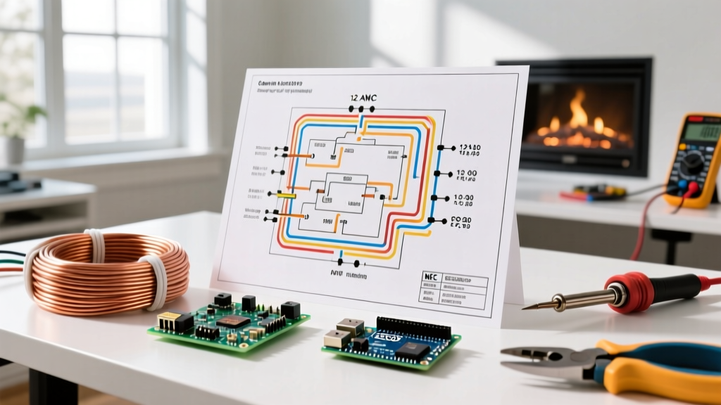
Whether you are working with a plug-in insert or a hardwired built-in model, the internal wiring diagram of an electric fireplace generally routes power to three primary subsystems: the heating element (resistive load), the blower motor (inductive load), and the LED/control board (electronic load).
Standard 120V Schematic Layout
For standard 120V units, the wiring diagram is straightforward and mirrors a standard residential branch circuit:
- Line (Hot): Black wire from the breaker panel connects to the fireplace terminal marked 'L' or 'Line'.
- Neutral: White wire connects to the terminal marked 'N' or 'Neutral'. This is critical for completing the circuit for the 120V blower motor and the low-voltage transformer that powers the LED flame effects.
- Ground: Bare copper or green wire connects to the chassis ground screw or the 'G' terminal. Never bypass this connection; the metal chassis of the fireplace must be bonded to the equipment grounding conductor.
240V Hardwired Schematic Layout
Larger, built-in architectural fireplaces often require 240V to deliver up to 5,000 BTUs of heat output efficiently. The wiring diagram for a 240V electric fireplace differs significantly:
- Line 1 & Line 2: Black and Red wires from a double-pole breaker connect to 'L1' and 'L2'. These provide the 240V across the primary heating element.
- Neutral (Conditional): Purely resistive 240V heaters do not require a neutral. However, modern smart fireplaces with Wi-Fi modules, thermostats, and 120V blower motors do require a neutral (White wire) to step down the voltage for the control electronics. Always verify the manufacturer's schematic before omitting the neutral wire.
- Ground: Bare copper to the chassis ground.
120V Plug-In vs. 240V Hardwired: Planning Matrix
Choosing between a 120V and 240V configuration dictates your entire rough-in strategy. Use the comparison table below to determine which pathway aligns with your structural constraints and heating requirements.
| Feature | 120V Plug-In (NEMA 5-15) | 240V Hardwired (Direct Connect) |
|---|---|---|
| Max Heating Output | ~5,100 BTUs (1,500W) | ~8,500 to 17,000 BTUs (2,500W - 5,000W) |
| Room Coverage | Up to 400 sq. ft. | Up to 1,000+ sq. ft. |
| Circuit Requirement | Dedicated 15A or 20A 120V circuit | Dedicated 20A or 30A 240V double-pole circuit |
| Installation Cost (Avg) | $0 - $250 (if outlet exists) | $350 - $800 (new breaker, cable run, junction box) |
| Aesthetic Finish | Visible cord (unless recessed outlet is installed) | Completely seamless, zero visible wires |
Wire Gauge and Breaker Sizing Guide
Undersizing your wire or breaker is a severe fire hazard, while oversizing can lead to improper breaker trip curves and damaged internal fireplace fuses. The U.S. Consumer Product Safety Commission (CPSC) emphasizes that matching wire gauge to overcurrent protection is the primary defense against electrical fires. Refer to this matrix based on NEC Article 210 and 240:
| Fireplace Wattage | Voltage | Max Amps | Required Breaker | Minimum NM-B Cable |
|---|---|---|---|---|
| 1,500W | 120V | 12.5A | 15A Single-Pole | 14/2 AWG (12/2 recommended) |
| 1,800W | 120V | 15.0A | 20A Single-Pole | 12/2 AWG |
| 2,500W | 240V | 10.4A | 15A Double-Pole | 14/2 AWG (12/2 recommended) |
| 3,500W | 240V | 14.5A | 20A Double-Pole | 12/2 AWG |
| 5,000W | 240V | 20.8A | 30A Double-Pole | 10/2 AWG |
Pro-Tip for 2026 Installations: Always default to 12/2 AWG for 120V runs and 10/2 AWG for 240V runs under 30A, even if 14 AWG or 12 AWG is technically permitted by code. The marginal material cost increase (roughly $15-$30 per 250ft spool) drastically reduces voltage drop over long runs and provides future-proofing for higher-wattage replacements.
Step-by-Step Hardwired Installation Workflow
If your planning dictates a 240V hardwired installation, follow this precise workflow to ensure a safe, code-compliant termination.
- Panel Shutdown and Verification: Turn off the main breaker or the specific double-pole breaker. Use a non-contact voltage tester (NCVT) and a digital multimeter (like the Fluke 117) to verify zero voltage at the junction box.
- Rough-In the Junction Box: Install a 4-inch square, 2-1/8-inch deep metal or heavy-duty PVC junction box inside the fireplace framing. Ensure it is accessible; NEC Article 314.29 strictly prohibits burying junction boxes behind drywall or the fireplace unit itself.
- Pulling the Cable: Route your NM-B (Romex) cable from the panel to the junction box. Leave at least 8 inches of slack inside the box. Secure the cable within 8 inches of the box using appropriate cable staples.
- Stripping and Prepping: Strip the outer jacket, leaving the individual wire insulation intact. Strip 3/4 inch of insulation from the black, red, and white wires. Crimp ferrule connectors or tin the ends if the fireplace uses European-style terminal blocks to prevent strand fraying.
- Termination: Connect Black to L1, Red to L2, White to Neutral (if required by schematic), and Bare to the Ground screw. Torque terminal screws to the manufacturer's specification (typically 1.2 Nm to 1.5 Nm) using a calibrated torque screwdriver to prevent loose connections that cause arcing.
- Final Testing: Restore power at the panel. Before sliding the fireplace unit into the framing, test the voltage at the terminal block. You should read ~240V across L1 and L2, and ~120V from either Line to Neutral/Ground.
Common Failure Modes and Edge Cases
Even with a perfect wiring diagram execution, environmental and circuit variables can cause operational failures. Anticipate these edge cases during your planning phase:
GFCI Nuisance Tripping
If your local jurisdiction requires GFCI protection for the room (common in basements or additions), be aware that the heavy resistive heating elements and inductive blower motors in electric fireplaces can generate harmless leakage currents. This can cause standard GFCI breakers to nuisance trip when the heater kicks on. Solution: Use a dedicated circuit without GFCI if local code permits for fixed heating appliances, or install a high-quality, industrial-grade GFCI breaker (like the Square D QO220GFI) designed to handle motor inrush currents.
Voltage Drop on Long Cable Runs
If your electrical panel is located on the opposite side of the house, and the cable run exceeds 75 feet, voltage drop becomes a critical factor. A 5% voltage drop on a 240V circuit reduces the voltage to 228V, causing the heating element to underperform and the blower motor to overheat. Solution: For runs over 75 feet, bump the wire gauge up one size (e.g., use 10/2 AWG instead of 12/2 AWG for a 20A circuit).
Smart Home Integration Wiring
Many homeowners in 2026 want to integrate their fireplace with smart home ecosystems (HomeKit, Alexa, Matter). If you plan to wire a smart relay (like a Shelly Plus 1PM or an Aeotec Nano Switch) behind the fireplace to control the main power, you must ensure a neutral wire is present in the junction box, even for 240V units. Most smart relays require 120V to power their internal Wi-Fi/Z-Wave radios.
NEC Code Compliance and Safety Clearances
Beyond the electrical connections, the physical installation must adhere to strict clearance codes. The U.S. Department of Energy recommends verifying appliance clearances to maintain energy efficiency and prevent thermal degradation of surrounding materials.
- Combustible Clearances: Maintain a minimum of 12 inches of clearance from the top of the fireplace unit to any combustible mantel or shelving, unless the manufacturer's specific UL listing dictates otherwise.
- Thermal Insulation: Do not pack fiberglass or foam insulation tightly against the rear or sides of the fireplace chassis. These units require convective airflow to dissipate heat from the internal electronics. Leave a minimum 1-inch air gap on all non-combustible sides.
- Dedicated Circuit Rule: NEC Article 210.23 limits the utilization of branch circuits. A fixed electric fireplace drawing over 50% of the circuit's capacity (e.g., a 1,500W heater on a 15A/1,800W circuit) must be on a dedicated circuit. It cannot share a breaker with lighting, televisions, or vacuum outlets.
By thoroughly reviewing the wiring diagram for your electric fireplace and planning your circuit infrastructure around these precise specifications, you guarantee a safe, high-performance installation that will provide reliable warmth and ambiance for years to come. Always consult with a licensed master electrician if your local municipality requires a permit and final inspection for new 240V branch circuits.