
The True Cost of Blind Troubleshooting
When a circuit fails, the average homeowner or junior technician resorts to 'shotgun troubleshooting'—randomly replacing receptacles, swapping breakers, and pulling wire nuts until the issue resolves. This approach wastes time and money. A standard residential electrician diagnostic fee ranges from $150 to $300 just to walk through the door. By mastering how to read an electrical installation wiring diagram, you can systematically isolate faults, reducing a three-hour guessing game into a 20-minute targeted repair. Whether you are dealing with a tripped AFCI breaker, a dead daisy-chained receptacle, or a flickering multi-way switch, the diagram is your definitive roadmap.
Anatomy of a Modern Electrical Installation Wiring Diagram
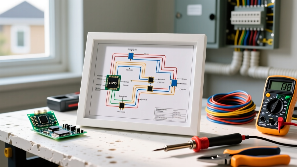
Before grabbing a multimeter, you must understand the language of the diagram. Unlike a pure schematic (which shows logical current flow), an electrical installation wiring diagram maps the physical routing and interconnections of the actual hardware. According to the NFPA 70 National Electrical Code (NEC), standard symbols dictate how devices are represented, but as-built diagrams often include physical annotations.
Key Elements to Identify
- Panel Schedule & Circuit Numbers: The diagram will label circuits (e.g., 'Circuit 14 - Kitchen Small Appliance'). Always verify the physical panel directory matches the diagram, as previous owners often swap breakers without updating the paper.
- Cable Types & Gauges: Look for notations like '12/2 NM-B' (12 AWG, 2 conductors with ground, Non-Metallic Sheathed) or '14/3 NM-B'. This tells you the breaker size limit (20A for 12 AWG, 15A for 14 AWG) and whether a multi-wire branch circuit (MWBC) is present.
- Splice & Junction Points: Diagrams use specific nodes or 'J-Box' icons to indicate where wires are marretted together. These are prime failure points for loose neutrals or melted wire nuts.
The 'Half-Split' Troubleshooting Method
The most efficient way to use an electrical installation wiring diagram for a dead circuit is the 'Divide and Conquer' or 'Half-Split' method. If a diagram shows a 20A branch circuit feeding six daisy-chained duplex receptacles in a living room, do not test them sequentially from the panel.
- Locate the Midpoint: Identify the 3rd receptacle on the diagram. This is your physical and logical midpoint.
- Test the Midpoint: Using a digital multimeter (DMM), test for 120V AC between the hot (brass) and neutral (silver) terminals at the 3rd receptacle.
- Interpret the Result: If you read 0V, the fault lies upstream (between the panel and receptacle 3). If you read 120V, the fault lies downstream (between receptacle 3 and 6). You have instantly eliminated 50% of the circuit from your troubleshooting path.
- Repeat: Split the remaining faulty half in half again until you isolate the exact segment or device.
Common Failure Modes & Diagram Tracing Matrix
Below is a diagnostic matrix mapping common residential symptoms to specific tracing points on your electrical installation wiring diagram. This data assumes standard 120V split-phase residential systems.
| Symptom | Diagram Trace Point | Probable Cause | Verification Method |
|---|---|---|---|
| Breaker trips instantly upon reset | Trace hot path for direct neutral/ground cross or 'backstabbed' connections | Dead short or ground fault; melted insulation at a staple point | Disconnect load at first device. Use Fluke 117 to measure continuity between hot and ground (should be infinite/OL). |
| Voltage drops to 90V under load | Check wire gauge notation (e.g., 14 AWG on a long run >50ft) | Excessive voltage drop (NEC recommends max 3% for branch circuits) or loose neutral | Measure voltage at panel, then at receptacle while running a 1500W space heater. A drop >5V indicates high resistance. |
| GFCI trips randomly, no load attached | Trace downstream 'LOAD' terminals to outdoor or wet-location receptacles | Moisture ingress in a downstream outdoor weatherproof box or degraded downstream wiring | Disconnect the 'LOAD' wires at the GFCI. If tripping stops, the fault is strictly downstream. |
| 3-Way switch operates in reverse or fails | Identify 'traveler' wires (usually red/black on 12/3 or 14/3 NM-B) | Travelers swapped with the common terminal, or a broken traveler wire inside the wall | Use a non-contact voltage tester (NCVT) to identify the constantly hot 'Line' wire, then map travelers with a continuity tester. |
Advanced Tracing: Multi-Wire Branch Circuits (MWBCs)
One of the most dangerous scenarios an electrician faces is an undocumented MWBC. An electrical installation wiring diagram will show two hot wires (typically black and red) sharing a single white neutral wire, originating from a double-pole breaker or two single-pole breakers with a handle tie.
Safety Warning: Per NEC Article 210.4, MWBCs require simultaneous disconnection. If a previous homeowner removed the handle tie and you only turn off the black hot wire to work on a receptacle, the shared neutral will still carry the return current from the red hot wire. Touching that neutral can result in a fatal 120V shock. Always use a clamp meter to check for neutral current before opening a junction box.
When troubleshooting an MWBC using the diagram, look for the 12/3 or 14/3 cable designation. If a receptacle on the black leg is dead, but the red leg is live, verify the 240V across the two hot wires at the panel to ensure both poles of the split-phase system are energized.
Essential Tools for Diagram-Based Troubleshooting
To execute the steps above, you need reliable test equipment. Cheap testers yield phantom voltages that lead to misdiagnosis. Here is the professional toolkit for 2026:
- Fluke T6-1000 Electrical Tester (~$230): Features FieldSense technology, allowing you to measure voltage and current through the wire insulation without metal-to-metal contact. Invaluable for tracing hot wires in crowded panels without exposing live bus bars.
- Klein Tools MM700 True RMS Multimeter (~$55): A rugged, CAT III/IV rated DMM perfect for half-split voltage testing and continuity checks on switch legs.
- Klein NCVT-3TI Non-Contact Voltage Tester (~$35): Dual-range (12V to 1000V) with a built-in flashlight. Essential for identifying which wire is the 'Line' and which is the 'Load' before removing a device from the wall.
- Southwire Tone & Probe Kit (~$45): When the electrical installation wiring diagram lacks physical cable labels, a tone generator helps trace a specific Romex cable through a finished wall or attic space.
Deciphering 'As-Built' Deviations
In commercial and high-end residential builds, the original electrical installation wiring diagram is often a 'design intent' document. Contractors frequently deviate due to framing obstacles, HVAC ductwork, or material shortages. When your diagram tracing fails to match physical reality, look for 'pigtails' in junction boxes. A junction box with four 12/2 NM-B cables entering it, rather than the two shown on the diagram, indicates the electrician used the box as a makeshift splice point to route around an obstruction. Always map these physical deviations onto your diagram using a red pen before closing up drywall or panel covers.
For comprehensive safety protocols before opening any panel or junction box, always adhere to OSHA's Lockout/Tagout (LOTO) standards. Verify zero energy state with a calibrated meter before making physical contact with any conductor.
Conclusion
An electrical installation wiring diagram is not just a piece of paper; it is a diagnostic algorithm. By combining the half-split testing method, understanding NEC code requirements for MWBCs, and utilizing True-RMS testing equipment, you can elevate your troubleshooting from amateur guesswork to professional-grade fault isolation. Always verify your physical findings against the diagram, document any as-built changes, and prioritize safety above speed.
For more detailed guides on reading specific panel schedules and motor control schematics, explore our extensive wiring diagram library and reference archives.