
Understanding the Standard Wiring Diagram for Fuel Gauge on Boat Systems
Marine electrical systems operate in one of the most unforgiving environments for electronics. When diagnosing or installing a marine fuel level system, relying on a generic automotive schematic is a critical mistake. A proper wiring diagram for fuel gauge on boat applications must account for ignition-switched power, dedicated grounding paths to prevent stray current corrosion, and precise variable resistance matching between the dash gauge and the in-tank sender unit.
In this comprehensive reference guide, we break down the exact circuit topology, terminal pinouts, and the crucial ohm-range compatibility matrix required to ensure your Faria, Sierra, or VDO gauge reads accurately from empty to full. Whether you are rewiring a 1990s center console or outfitting a 2026 pontoon, these principles remain the bedrock of marine instrumentation.
Core Circuit Topology: From Battery to Sender
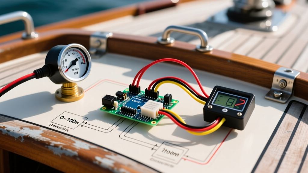
The standard marine fuel gauge circuit is a simple series circuit utilizing a variable resistor (the sender) to modulate current flow through the gauge's internal movement mechanism (typically an air-core or bimetallic motor). Unlike automotive systems that often rely on the vehicle's chassis for a ground return, marine systems must use a dedicated negative return wire to the DC ground bus.
The 4-Terminal Gauge Pinout
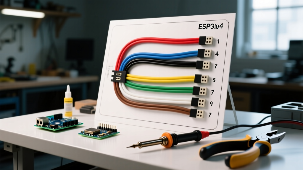
Most standard marine fuel gauges feature four blade terminals on the rear housing. Below is the industry-standard color code and function mapping, compliant with ABYC (American Boat & Yacht Council) wiring standards.
| Terminal Letter | Function | Standard Wire Color | Source / Destination |
|---|---|---|---|
| I | Ignition (Power In) | Purple | Ignition Switch (Switched 12V+) |
| S | Sender (Signal) | Pink | Fuel Sender 'S' Terminal |
| G | Ground (Power Out) | Black | DC Negative Ground Bus |
| L | Illumination | Blue or White | Navigation Light Switch (Optional) |
Pro-Tip for 2026 Restorations: Never wire the gauge 'G' terminal directly to the metal dash panel. Always route a dedicated 16 AWG black wire back to the main negative busbar. Dash panels on fiberglass boats do not provide a reliable ground, and aluminum panels can cause galvanic corrosion if used as a current return path.
The Critical Variable: Sender Ohm Range Compatibility
The most common reason a newly installed marine fuel gauge reads backwards, pegs to 'Full', or stays on 'Empty' is an ohm mismatch. The fuel sender is a float attached to a resistive card. As the float moves, the resistance changes. If the gauge expects a 0-190 ohm range but receives a 240-33 ohm signal, the internal magnetic fields will not align correctly with the float position.
Before pulling any wires, you must verify the ohm range of your in-tank sender. According to Faria Beede Instruments technical documentation, mismatched senders and gauges account for over 70% of 'defective' gauge returns.
Marine Fuel Sender Compatibility Matrix
| Standard Type | Empty Resistance | Full Resistance | Common Brands / Applications |
|---|---|---|---|
| US Standard | 240 Ohms | 33 Ohms | Most US-built boats, Mercury, OMC, standard Faria/Sierra gauges |
| European | 0 Ohms | 190 Ohms | VDO, European imports, some Volvo Penta setups |
| VDO / Medallion | 10 Ohms | 180 Ohms | Specific VDO gauges, older Medallion systems |
| European (Alt) | 0 Ohms | 300 Ohms | Some late-model European diesel applications |
Step-by-Step Wiring and Installation Procedure
To ensure longevity and prevent voltage drop, use high-quality marine-grade components. In 2026, premium tinned copper wire (such as Ancor Marine Grade wire) costs approximately $0.80 to $0.95 per foot for 16 AWG, a worthwhile investment over standard automotive copper which will rapidly oxidize (turn black) in a bilge environment.
Required Tools and Materials
- 16 AWG Tinned Marine Wire (Purple, Pink, Black, Blue)
- Adhesive-lined heat shrink ring terminals (AWG 22-16)
- Heat gun (do not use an open flame lighter)
- Digital Multimeter (DMM) with resistance (Ohms) and DC Voltage settings
- Inline AGC/ATO fuse holder with a 3A or 5A fuse
Execution Steps
- Disconnect the Battery: Isolate the DC negative and positive terminals at the main battery bank to prevent accidental short circuits while working behind the helm.
- Fuse the Power Source: ABYC E-11 standards dictate that overcurrent protection must be placed within 7 inches of the power source. Install a 3A inline fuse on the purple ignition wire as close to the ignition switch output as possible.
- Route the Harness: Run the 4-wire bundle from the helm to the fuel tank. Keep the pink sender wire separated from high-current cables (like bilge pump or starter cables) by at least 2 inches to prevent electromagnetic interference (EMI), which can cause erratic gauge needle movement.
- Terminate the Sender Connections: At the fuel tank, connect the Pink wire to the 'S' terminal on the sender, and the Black wire to the 'G' terminal. Crimp using adhesive-lined heat shrink terminals and apply heat until the adhesive seals the wire insulation.
- Connect the Gauge: At the helm, attach the Purple wire to 'I', Pink to 'S', Black to 'G', and Blue to 'L' (if illumination is desired). Secure the connections with the provided hex nut, ensuring no stray wire strands are shorting against adjacent terminals.
- Voltage Drop Test: Reconnect the battery and turn the key to the 'ON' position. Use your DMM to measure the voltage between the gauge 'I' terminal and the 'G' terminal. It should read within 0.2V of your battery voltage (e.g., 12.4V). If it reads 11.5V or lower, you have high resistance in the wiring or a poor ground.
Troubleshooting Common Fuel Gauge Faults
When the needle refuses to cooperate, use this diagnostic matrix to isolate the failure point without immediately replacing the gauge or sender.
Scenario 1: Gauge Pegs to 'FULL' Regardless of Fuel Level
Root Cause: In a US Standard (240-33 ohm) system, the gauge reads full when resistance approaches zero. A pegged gauge indicates a dead short to ground on the Pink signal wire, or the sender float is physically stuck at the top of the resistive card.
Diagnostic Step: Disconnect the Pink wire from the 'S' terminal on the back of the gauge. If the needle immediately drops to 'Empty', the short is in the wiring harness or the sender itself. Inspect the sender terminal for moisture ingress causing a short across the pins.
Scenario 2: Gauge Reads 'EMPTY' When Tank is Full
Root Cause: An open circuit on the Pink wire, a broken ground wire at the sender, or an ohm mismatch (e.g., using a 0-190 sender with a 240-33 gauge).
Diagnostic Step: Turn off the ignition. Set your multimeter to the 200 Ohms range. Measure resistance between the Pink wire (disconnected at the gauge) and a known good ground. You should see a reading between 33 and 240 ohms depending on the actual fuel level. If the meter reads 'OL' (Open Loop), the Pink wire is broken or the sender ground is disconnected.
Scenario 3: Needle is Erratic or Bounces While Underway
Root Cause: Fuel sloshing in the tank is normal, but violent bouncing indicates a failing resistive card inside the sender (worn spots causing momentary open circuits) or a loose crimp connection vibrating behind the dash.
Diagnostic Step: Most modern marine gauges feature an internal damping circuit or a physical friction clip on the needle. If the wiring tests solid, the sender's wiper arm is likely worn. Replacing the sender unit (typically $45 to $85 for a standard Moeller or Attwood 5-hole pattern sender) is the only permanent fix.
Final System Verification
After completing the wiring, perform a full sweep test. If your tank is accessible, manually move the sender arm from the bottom of the travel arc to the top while observing the dash. The needle should track smoothly without dead spots. By strictly adhering to this wiring diagram for fuel gauge on boat configurations and respecting the marine-specific ohm ranges, you ensure accurate fuel monitoring and eliminate the risk of running dry miles from the dock.