
The Standard Wiring Diagram for 7 Pin Trailer Connector Setups
When towing heavy loads, travel trailers, or equipment haulers, the electrical connection is just as critical as the physical hitch. The 7-pin trailer connector (commonly referred to as the 7-way RV blade) is the North American standard for towing applications requiring electric brakes, auxiliary 12V power, and reverse lighting. Understanding the correct wiring diagram for 7 pin trailer connector configurations is not just about matching colors; it is about selecting the proper wire gauge to prevent voltage drop, overheating, and catastrophic brake failure on the highway.
Unlike older 4-pin flat connectors that only handle basic lighting, the 7-pin setup integrates high-amperage circuits. According to SAE International Standard J286, which governs trailer connector pinouts and color codes, specific functions must be mapped to precise terminals. However, the SAE standard does not strictly mandate wire gauge, leaving that critical safety decision to the installer. Below is the definitive reference for wiring, color coding, and gauge selection for modern towing applications in 2026.
SAE J286 Color Code & Pinout Matrix
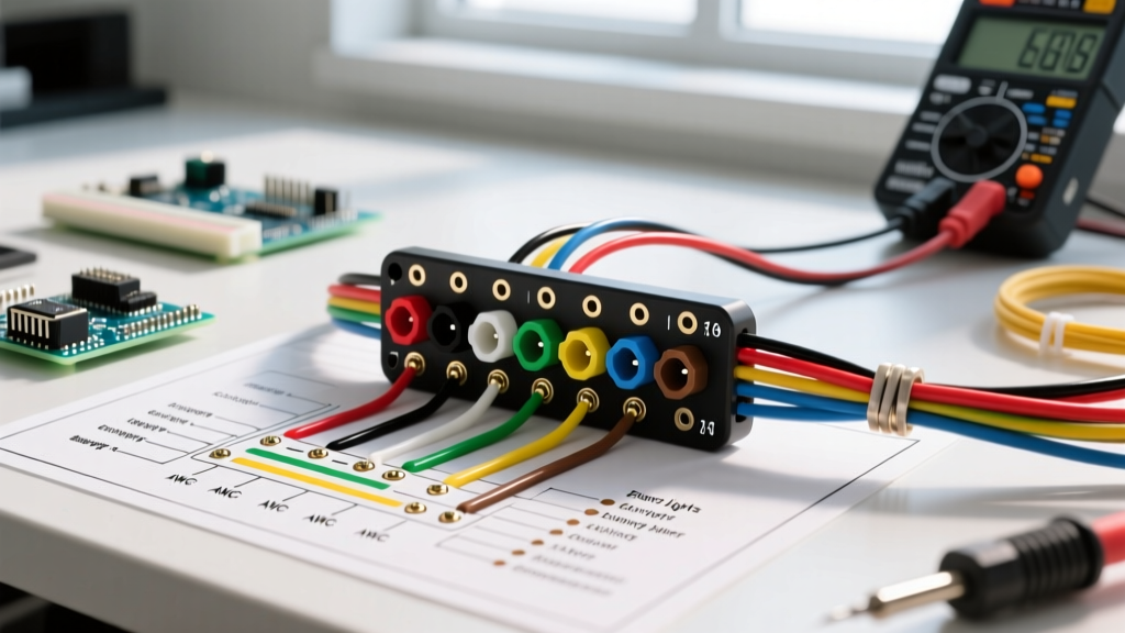
The following table outlines the standard RV 7-way flat blade pinout. Note that while the SAE color codes are standard, some aftermarket harnesses may deviate. Always verify with a multimeter before final termination.
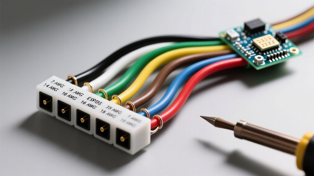
| Pin / Clock Position | Function | SAE Wire Color | Recommended Wire Gauge (AWG) | Max Continuous Load |
|---|---|---|---|---|
| Pin 1 (7:00) | System Ground | White | 10 AWG or 8 AWG | 30A - 40A |
| Pin 2 (1:00) | Tail / Running Lights | Brown | 14 AWG | 7A |
| Pin 3 (9:00) | Left Turn / Stop | Yellow | 14 AWG | 10A |
| Pin 4 (3:00) | Right Turn / Stop | Green | 14 AWG | 10A |
| Pin 5 (5:00) | Electric Trailer Brakes | Blue | 10 AWG | 20A - 30A |
| Pin 6 (11:00) | 12V Auxiliary / Charge | Black (or Red) | 10 AWG or 8 AWG | 30A - 40A |
| Pin 7 (Center) | Reverse Lights / Aux | Purple | 14 AWG | 10A |
Wire Gauge Selection: Sizing for Brake Controllers and Auxiliary Power
The most common and dangerous mistake DIYers make when wiring a 7-pin connector is using 14 AWG or 16 AWG wire for the electric brake and 12V auxiliary circuits. While 14 AWG is perfectly adequate for LED tail lights (which draw less than 2 amps total), it is entirely insufficient for dynamic, high-draw loads.
The Math Behind Electric Trailer Brakes
A standard 12-inch electric trailer brake assembly (such as the popular Dexter Nev-R-Adjust 23-469) draws approximately 3.5 to 4.0 amps at 12V DC when fully engaged. If you are towing a dual-axle trailer with four brake assemblies, your brake controller will push up to 16 amps continuously during a hard stop. If you are towing a triple-axle gooseneck with six brakes, that number jumps to 24 amps.
According to ampacity guidelines adapted from the NFPA 70 National Electrical Code for DC chassis wiring, 14 AWG copper wire is rated for roughly 15 amps. Pushing 24 amps through a 14 AWG blue wire over a 30-foot run will result in two major issues:
- Severe Voltage Drop: By the time the current reaches the trailer axles, the voltage may drop below 9V. Electric brakes rely on voltage to modulate magnetic force; low voltage means weak braking, directly violating FMCSA Title 49 Section 393.40 safety regulations regarding brake actuation performance.
- Thermal Degradation: The wire insulation will heat up, eventually becoming brittle, cracking, and causing a short circuit against the trailer frame.
The Solution: Always use 10 AWG stranded copper wire for the Blue (brakes), Black (12V aux), and White (ground) circuits. For trailers exceeding 35 feet in length, upgrade the brake and ground circuits to 8 AWG to mitigate voltage drop over the extended distance.
Heavy-Duty Termination: Tools and Techniques for 2026
A wiring diagram is only as good as the physical connections it represents. The environment under a trailer is brutal, subjected to road salt, water immersion, and constant vibration. Standard butt connectors and electrical tape will fail within a single season.
Required Tooling and Materials
- Crimpers: Use a ratcheting crimping tool designed for non-insulated or heat-shrink terminals. The Knoweasy Heavy Duty Ratcheting Crimper (approx. $35) or the Titan 11477 provides the necessary 2,000+ lbs of crimping force to ensure a cold-weld bond between the copper strands and the terminal barrel.
- Terminals: Use adhesive-lined, dual-wall heat shrink ring terminals. The inner wall contains a thermoplastic adhesive that melts and seals the wire strands, preventing capillary action from wicking moisture up the wire jacket.
- Dielectric Grease: Apply a generous amount of silicone dielectric grease (e.g., CRC Industries or Permatex) to the 7-pin plug terminals to prevent galvanic corrosion between the brass pins and the steel socket.
Expert Tip: Never use solid core wire for trailer wiring. Trailers experience high-frequency vibration and chassis flexing. Solid core wire will work-harden, snap, and fail internally while the outer insulation looks perfectly intact. Always use multi-strand, flexible automotive-grade GXL or TXL cross-linked polyethylene (XLPE) insulated wire, which is rated for high temperatures and abrasion resistance.
Step-by-Step Wiring & Routing Best Practices
- Prepare the Harness: Cut your 7-conductor trailer cable to length, leaving at least 3 feet of slack between the trailer tongue and the frame to allow for tight turning radii without pulling the plug from the tow vehicle's socket.
- Strip and Crimp: Strip exactly 3/8-inch of insulation from the wire ends. Insert into the appropriate gauge ring terminal and crimp using the ratcheting tool. Tug firmly (at least 15 lbs of force) to verify the crimp.
- Heat Shrink Application: Apply heat evenly using a heat gun (not a lighter) until the adhesive oozes slightly from the edges of the shrink tube.
- Frame Routing: Run the wiring harness through the trailer's C-channel frame rails. Use UV-resistant nylon zip ties or rubber-lined P-clamps every 18 inches. Avoid routing wires near hot exhaust components or sharp, unpainted metal edges.
- The Ground Connection: The white ground wire must be terminated to a clean, bare metal surface on the trailer frame. Sand away all paint, rust, and powder coating. Use a stainless steel self-tapping screw or a bolt with a star washer to bite into the steel. Never rely on the hitch ball and coupler to complete the ground circuit.
Diagnosing Common 7-Pin Failure Modes
Even with a perfect wiring diagram for 7 pin trailer connector setups, environmental factors can cause faults. Here is how to troubleshoot the three most common failure modes:
1. The 'Ghost Light' or Dimming Issue
Symptom: When you press the brake pedal, the trailer's running lights dim, or the turn signals flash rapidly on the tow vehicle's dashboard.
Diagnosis: This is a classic ground fault. The electrical current is seeking an alternative path to ground, often back-feeding through the tail light circuit. Clean the main white ground connection on the trailer tongue and verify continuity between the trailer frame and the negative battery terminal of the tow vehicle.
2. Weak or Pulsing Electric Brakes
Symptom: The brake controller (e.g., Curt Spectrum or Redarc Tow-Pro Elite) shows output, but the trailer brakes feel weak or grab inconsistently.
Diagnosis: Check for voltage drop on the Blue wire. With the brake controller manually overridden to 100% output, use a multimeter to measure voltage at the trailer's brake hub. If the tow vehicle is outputting 12.5V but the hub only receives 9.8V, you have undersized wiring or severe corrosion at the 7-pin socket. Upgrade the blue wire to 8 AWG and clean the socket pins.
3. 12V Auxiliary Circuit Tripping the Tow Vehicle
Symptom: Plugging in the trailer immediately blows the 30A or 40A auxiliary fuse in the tow vehicle's under-hood power distribution box.
Diagnosis: The Black (12V aux) wire is shorting to ground, or the trailer's breakaway battery is completely dead and pulling infinite amperage to charge. Disconnect the trailer's breakaway battery and interior loads. Test the Black wire for continuity to ground. If it shorts, inspect the wiring near the trailer tongue where it is most susceptible to rock strikes and abrasion.
Summary: Safety Through Precision
Building or repairing a trailer harness requires strict adherence to the SAE color codes and, more importantly, rigorous wire gauge selection. By utilizing 10 AWG for high-draw circuits, employing adhesive-lined heat shrink terminations, and establishing a dedicated, paint-free ground path, you ensure that your trailer's lighting and braking systems perform flawlessly under the most demanding highway conditions. Always verify your final connections with a digital multimeter and a dedicated 7-pin trailer circuit tester before taking your rig on the road.