
Understanding the Starter Solenoid: The Heavy-Duty Relay
When you turn your ignition key, the starter motor requires a massive surge of direct current—often between 150 and 250 amps—to overcome engine compression. Your ignition switch cannot handle this load; attempting to route that much current through the steering column would melt the wiring harness. This is where the starter solenoid comes in. It acts as a heavy-duty, remote-controlled relay that bridges the high-current battery circuit to the starter motor using a low-current trigger signal.
However, interpreting a wiring diagram for a starter solenoid can be confusing for DIY mechanics and marine electricians, primarily because of the physical variations in solenoid designs. A miswired solenoid won't just fail to crank your engine; it can cause parasitic battery drains, melt control wires, or permanently weld the internal contacts, causing the starter to spin uncontrollably even after you release the key.
The Intermittent vs. Continuous Duty Trap
Before pulling any wire, you must verify the duty cycle of your solenoid. This is the most common point of failure in custom builds, tractor restorations, and marine applications.
- Intermittent Duty (Standard Automotive): Designed to be energized for only 15 to 30 seconds at a time. The internal copper windings are not potted or cooled for sustained use. Examples include the Standard Motor Products SS508 or Delco Remy DR-2.
- Continuous Duty (Golf Carts, Winches, Hydraulics): Built with heavier gauge windings and often oil-filled or potted to dissipate heat over minutes or hours of use. Examples include the Cole Hersee 24063.
Expert Warning: Never use an intermittent-duty automotive solenoid for a winch or continuous hydraulic pump. The coil will overheat and short out internally within minutes, potentially causing a fire.
3-Post vs. 4-Post: Decoding the Terminals
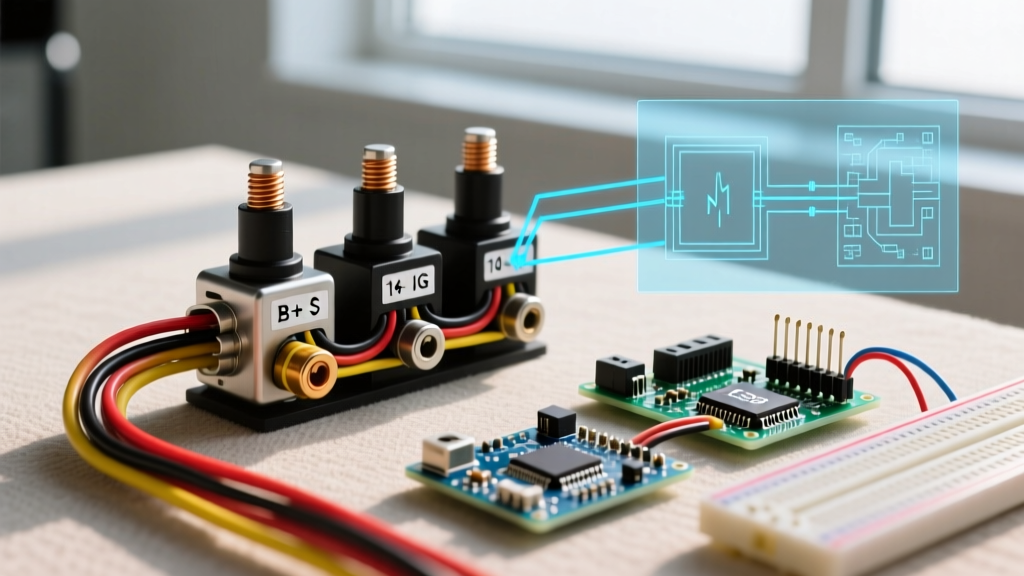
The physical layout of your solenoid dictates the exact wiring diagram you must follow. The two dominant architectures are the GM-style 3-post and the Ford-style 4-post.
| Feature | GM-Style (3-Post) | Ford-Style (4-Post) |
|---|---|---|
| Grounding Method | Internal ground (through mounting bracket) | External ground (requires dedicated 4th terminal) |
| High Current Terminals | B (Battery) and M (Motor) | B (Battery) and M (Motor) |
| Trigger Terminal | S (Start trigger from ignition) | S (Start trigger from ignition) |
| Ignition Bypass | R or I (Sends 12V to coil during crank) | N/A (Handled externally or not required on EFI) |
| Mounting Requirement | Must mount to clean, bare metal | Can mount to painted surfaces or fiberglass |
Required Tools and Material Specifications
Do not rely on cheap, stamped-steel terminals for high-current circuits. Inrush current will arc and pit poor connections. Gather the following specific materials:
- High-Current Cable: 1/0 AWG or 2 AWG stranded copper (SAE J1128 rated) for the Battery (B) and Motor (M) connections.
- Control Wire: 10 AWG or 12 AWG primary wire (TXL cross-linked insulation) for the 'S' trigger circuit.
- Terminals: Heavy-duty copper lugs with 3/8" inner diameter. Avoid aluminum or copper-clad aluminum (CCA).
- Crimping Tool: A dedicated hex-crimp die tool (like the Knipex 97 51 10 or Titan 11500). Pliers will not provide the necessary cold-weld compression.
- Sealing: Dual-wall adhesive heat shrink (e.g., 3M MDT) to prevent moisture wicking into the copper strands.
- Anti-Oxidant: NO-OX-ID A-Special conductive grease to prevent galvanic corrosion on the studs.
Step-by-Step Wiring Walkthrough
Step 1: Isolate the Power Source
Disconnect the negative battery terminal first. In a marine or off-grid environment, physically remove the negative cable from the battery bank and secure it away from the post. A starter solenoid is directly connected to the un-fused positive battery feed; a dropped wrench across the B-terminal and chassis ground will instantly weld tools together and cause severe thermal burns.
Step 2: High-Current Battery and Motor Connections (Terminals B & M)
Locate the two large 3/8" or 5/16" threaded studs. On most solenoids, these are non-polarized regarding the magnetic coil, but standard practice dictates:
- Attach the cable coming directly from the positive battery terminal to the B (Battery) stud.
- Attach the cable running down to the starter motor to the M (Motor) stud.
- Apply a thin layer of NO-OX-ID A-Special to the threads and the contact face of the lugs.
- Torque the nuts to 9-12 ft-lbs for 3/8" studs, or 5-7 ft-lbs for 5/16" studs. Do not over-torque. The studs are pressed into a Bakelite or phenolic insulator cap; excessive force will crack the cap, leading to internal arcing and solenoid failure.
Step 3: Control Circuit Wiring (Terminal S)
The 'S' terminal is the low-current trigger. When you turn the key to 'Start', the ignition switch sends 12V to this spade or small screw terminal, energizing the internal pull-in and hold-in coils.
- Route a 10 AWG or 12 AWG wire from the ignition switch's 'Start' output to the 'S' terminal.
- Ensure this wire is routed away from exhaust headers and moving linkages. Use split-loom tubing and secure it every 8 inches with UV-resistant zip ties.
- If using a spade connector on the 'S' terminal, use a nylon-insulated female disconnect and crimp it with a ratcheting crimper to prevent vibration-induced disconnects.
Step 4: The Ignition Bypass Wire (Terminal I or R - GM 3-Post Only)
If you are wiring a classic vehicle with a points-style ignition system and a ballast resistor, the 'I' or 'R' terminal is critical. During cranking, the solenoid closes an internal bridge that sends full 12V from the B-terminal out through the I-terminal to the ignition coil, bypassing the ballast resistor for a hotter spark. Once the engine starts and you release the key, the I-terminal loses power, and the coil runs through the ballast resistor.
Note: Modern LS-swaps, EFI systems, and HEI distributors do not require the 'I' terminal. Simply cap it with a heat-shrunk butt connector to prevent accidental grounding.
Real-World Failure Modes and Edge Cases
Even with a perfect wiring diagram for a starter solenoid, physical degradation occurs. According to automotive diagnostic standards outlined by AA1Car, the most common failure is not the coil burning out, but the internal copper contact disc pitting and welding itself to the B and M terminals.
Voltage Drop Testing (The Only Accurate Diagnostic)
Do not rely on a multimeter's resistance (Ohms) setting to test a solenoid; the test leads' resistance will skew the data. Instead, perform a dynamic voltage drop test while cranking:
- Set your multimeter to DC Volts.
- Place the red probe on the B-terminal (battery side) and the black probe on the M-terminal (motor side).
- Have an assistant crank the engine.
- A healthy solenoid will show a voltage drop of 0.10V or less.
- If the drop exceeds 0.20V, the internal contacts are pitted, carbon-fouled, or melting. Replace the solenoid immediately.
Expert Troubleshooting FAQ
Why does the solenoid click rapidly but the engine won't crank?
This is the classic 'machine-gun' click. It indicates that the pull-in coil is receiving enough voltage to close the heavy contacts, but the moment the starter motor draws 200+ amps, the system voltage sags below the threshold required by the hold-in coil. The contacts open, voltage recovers, the coil pulls in again, and the cycle repeats. The fix is rarely the solenoid itself; it is usually undersized battery cables, corroded ground straps, or a weak battery. Check your cable gauge against SAE J1171 marine electrical standards for high-amperage DC routing.
Can I use a 4-post Ford solenoid on a GM application?
Yes, but you must manually ground the 4th terminal. A Ford-style solenoid relies on the 'I' (or ground) terminal to complete the coil circuit. If you mount it on a GM vehicle without running a dedicated ground wire from that 4th terminal to the chassis, the solenoid will not engage. Conversely, if you accidentally wire 12V to the ground terminal on a Ford solenoid, you will instantly fry the internal coil.
My starter stays engaged after I release the key. What happened?
Immediately disconnect the battery. This is a critical failure where the internal copper contact disc has physically welded itself to the B and M terminal posts due to excessive arcing. This usually happens when the solenoid is undersized for the starter motor's inrush current, or the return spring has fatigued. The solenoid must be replaced; it cannot be safely repaired.