
The Dual-Meter Approach in Mobile Electrical Platforms
Designing a robust electrical system for a recreational vehicle (RV) or a commercial mobile food truck requires precise energy monitoring. Unlike static residential builds, mobile platforms endure constant vibration, thermal cycling, and dual-power-source switching (shore power vs. onboard generators or inverters). Consequently, a standard residential meter is insufficient. In 2026, professional mobile upfitters rely on a dual-meter architecture: an AC sub-meter for utility billing and generator load-tracking, and a DC coulomb-counting shunt for lithium house bank management.
This guide provides the exact electricity meter wiring diagram specifications, torque values, and failure-mode mitigations required for high-end mobile builds, ensuring compliance with NFPA 1192 and local commercial health codes.
AC Sub-Metering: Carlo Gavazzi EM210-72 Wiring Diagram (120V/240V)
Commercial food trucks and long-term RV setups frequently require AC sub-metering. Health departments and RV parks often mandate visible metering to bill for shore power usage or to verify that onboard generators are not exceeding noise and emission thresholds under heavy load. The industry standard for compact, DIN-rail or panel-mount mobile AC metering is the Carlo Gavazzi EM210-72-CP paired with RCT23-03 100/5A Current Transformers (CTs).
Component Sourcing & 2026 Pricing
- Carlo Gavazzi EM210-72-CP: ~$245 (72x72mm panel mount, CT-connected)
- RCT23-03 100/5A CTs (x2 for split-phase): ~$65 each
- 14 AWG THHN Stranded Wire (Black, Red, White, Green): ~$0.45/ft
- Ferrule Crimp Kit (14 AWG): ~$35
Step-by-Step AC Wiring Sequence
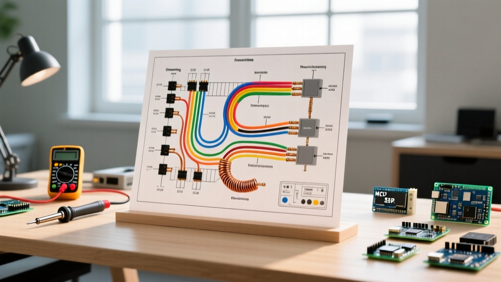
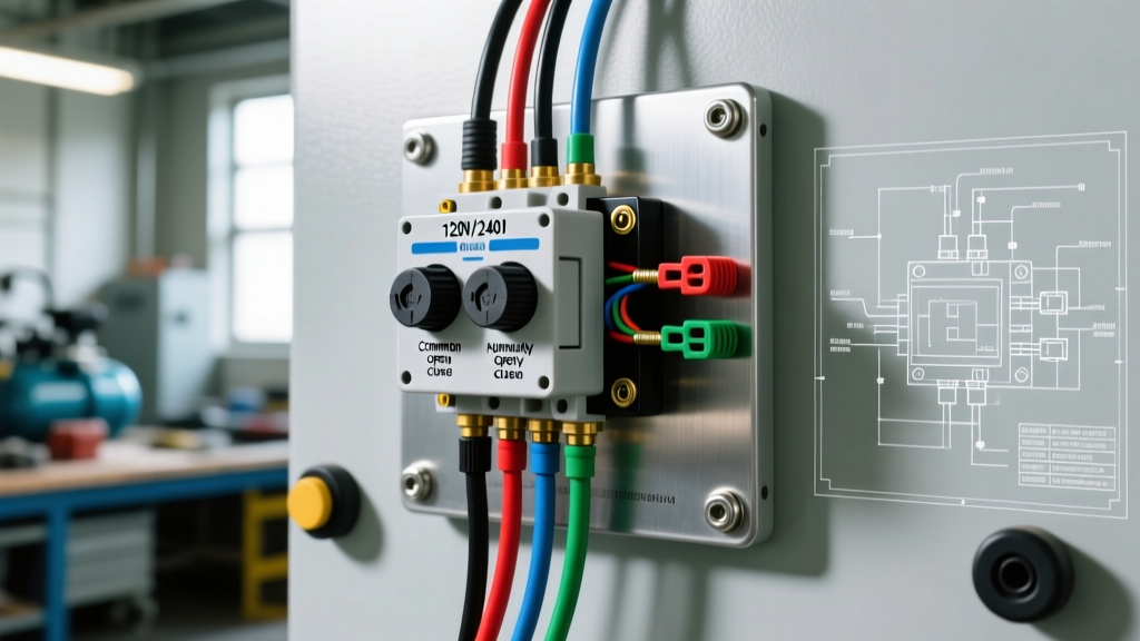
- Voltage Sense Routing: Run 14 AWG THHN from the main panel's L1, L2, and Neutral busbars to the meter's voltage terminals (V1, V2, V3, and VN). Crucial: Always install a 3-pole, 15A DIN-rail breaker upstream of the voltage sense wires to protect the meter's internal circuitry.
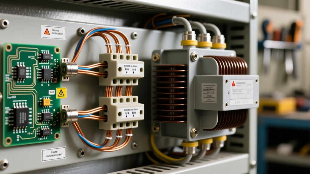
- Current Transformer (CT) Placement: Slide the L1 and L2 hot conductors through the center of the RCT23-03 CTs. The P1 arrow on the CT must point toward the load (away from the main breaker/shore power inlet).
- CT Secondary Wiring: Route the 14 AWG twisted-pair wires from the CTs to the meter's S1/S2 terminals. Use ferrule crimps on all stranded wire terminations to prevent fraying under vehicle vibration.
- Grounding: Terminate the meter's PE (Protective Earth) terminal to the vehicle's main chassis ground busbar using 10 AWG green wire.
⚠️ CRITICAL SAFETY WARNING: Never open-circuit a CT secondary while the primary conductor is under load. An open 100/5A CT can induce lethal voltages exceeding 2,000V, causing catastrophic insulation failure and arc flashes inside your mobile sub-panel. Always short the S1 and S2 terminals if the meter is removed while the system is live.
DC Coulomb Counting: Victron SmartShunt Wiring Diagram (12V/24V/48V)
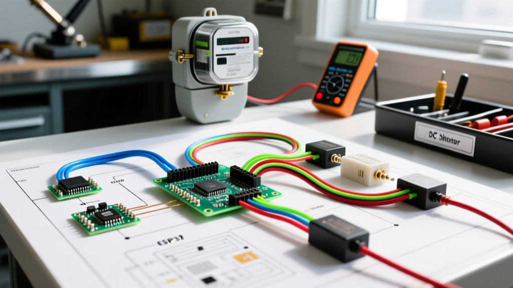
While AC metering tracks utility usage, DC metering is the lifeblood of an RV's off-grid capability. Voltage-based battery monitors are obsolete for LiFePO4 (Lithium Iron Phosphate) banks due to the flat discharge curve. A true DC electricity meter wiring diagram relies on a precision shunt. The Victron SmartShunt 500A/50mV remains the gold standard for 2026 mobile builds, offering Bluetooth telemetry and VE.Direct communication for BMS integration.
Busbar Integration & Torque Specifications
The SmartShunt must be the only connection to the negative terminal of the battery bank. All DC loads, inverter negatives, and solar charge controller negatives must land on the load-side busbar of the shunt.
- Cable Sizing: Use 2/0 AWG (70mm²) pure copper, Class K flexible marine cable for runs under 5 feet. For high-surge 48V inverter setups (e.g., Victron Quattro 10kVA), upgrade to 4/0 AWG to prevent shunt overheating.
- Termination: Use closed-end tubular lugs with a hex-crimp die. Avoid indent crimps, which loosen under the harmonic vibration of diesel engines and rough terrain.
- Torque Value: The M10 nuts on the SmartShunt require exactly 12 to 14 Nm of torque. Under-torquing causes micro-arcing and thermal runaway; over-torquing strips the brass threads inside the shunt block.
Auxiliary Sense & VE.Direct Routing
For dual-bank RV setups (e.g., a chassis start battery and a house bank), wire the 14 AWG auxiliary sense wire (with an inline 1A fuse) to the positive terminal of the start battery. Route the RJ45 VE.Direct cable to your inverter or GX device. Do not zip-tie the VE.Direct cable to 120V AC lines; maintain a minimum 4-inch separation to prevent electromagnetic interference (EMI) from corrupting the data stream.
Mobile Metering Comparison Matrix
| Feature | Carlo Gavazzi EM210 (AC) | Victron SmartShunt 500A (DC) |
|---|---|---|
| Primary Use Case | Shore power billing, generator load tracking | LiFePO4 State of Charge (SoC), BMS sync |
| Accuracy Class | Class 1 (IEC 62053-21) | ±0.3% (Current), ±0.01% (Voltage) |
| Max Continuous Current | 100A (via CTs) | 500A continuous / 1200A (10s surge) |
| Required Wire Gauge | 14 AWG (Sense & CT leads) | 2/0 AWG to 4/0 AWG (Main shunt path) |
| Approx. 2026 Cost | $375 (Meter + 2x CTs) | $145 (Shunt only) |
Critical Failure Modes & Troubleshooting
Mobile environments introduce unique electrical edge cases. If your electricity meter wiring diagram is executed poorly, you will encounter the following failure modes:
- Negative AC Wattage Readings: This almost always indicates a reversed CT. The P1/P2 orientation dictates current direction. If the P1 arrow points toward the shore power inlet instead of the load panel, the meter will register power as being 'exported' to the grid. Flip the CT physically or swap the S1/S2 wires at the meter terminal.
- DC Shunt Thermal Runaway: If the SmartShunt casing exceeds 60°C (140°F) during a 2,000W inverter draw, the cable lugs are likely undersized or improperly crimped. A poor crimp increases milliohm resistance at the terminal, turning the shunt block into a heater. Recrimp with a calibrated hex tool and apply antioxidant paste (e.g., NOALOX).
- Bluetooth Telemetry Dropouts: The SmartShunt relies on Bluetooth Low Energy (BLE). In metal-skinned Airstreams or aluminum food trucks, the BLE signal is trapped inside the Faraday cage of the chassis. Mount a Victron VE.Direct to Bluetooth dongle higher up in a non-metallic cabinetry section, or hardwire the VE.Direct to a Cerbo GX display.
- CT Saturation on Generator Startup: If your food truck uses a 100A CT but the AC compressor draws a 400A Locked Rotor Amp (LRA) surge on generator start, the CT core may saturate, temporarily blinding the meter. Use a 200A or 400A CT for circuits with heavy inductive motor loads to prevent core saturation.
Code Compliance & Authoritative References
When integrating metering into a mobile platform, adherence to safety codes is non-negotiable for insurance and inspection purposes. For RVs, NFPA 1192 (Standard on Recreational Vehicles) dictates strict rules on panel bonding, overcurrent protection, and chassis grounding. The AC sub-meter voltage sense wires must be protected by an appropriately rated breaker within 18 inches of the busbar tap.
For commercial food trucks, local health and fire marshals often reference NEC Article 530 or specific municipal mobile vending codes, which require lockable, tamper-evident enclosures for any metering used to bill commissary electricity. Always ensure your DIN-rail or panel-mounted meters are enclosed in a NEMA 3R or IP54-rated polycarbonate enclosure to withstand the high-pressure washdowns required in commercial food prep environments. For deeper technical specifications on industrial-grade mobile metering, refer to the Carlo Gavazzi Energy Metering catalog for exact CT saturation curves and wiring schematics.