
Introduction to VEVOR Single-Phase Motor Integration
VEVOR has become a dominant name in the DIY and light-industrial space, offering highly affordable single-phase AC motors (typically ranging from 1HP to 5HP) for lathes, air compressors, and agricultural equipment. However, unboxing a VEVOR 2HP 56C-frame motor and attempting to wire it directly to a standard household receptacle is a recipe for tripped breakers, melted insulation, or severe voltage drop. To safely integrate these motors into your workshop, you must thoroughly understand the VEVOR electric motor wiring diagram and correctly size your breaker panel infrastructure according to the National Electrical Code (NEC).
This guide bridges the gap between the manufacturer's terminal schematic and your main electrical panel. We will cover exact terminal designations, NEC Article 430 compliance for branch circuits, breaker sizing matrices, and the critical integration of magnetic motor starters to protect your investment.
Decoding the VEVOR Electric Motor Wiring Diagram
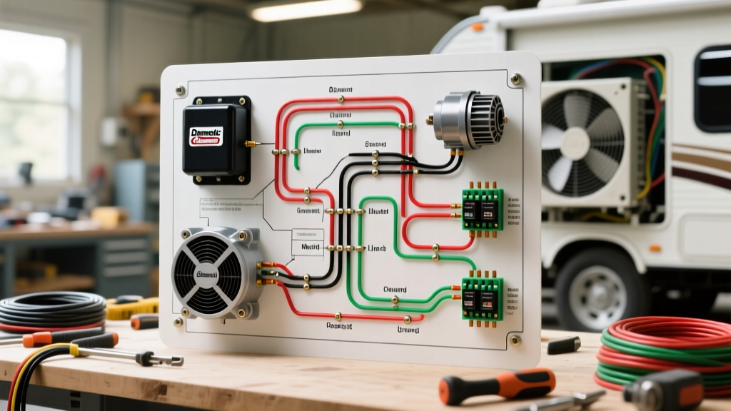
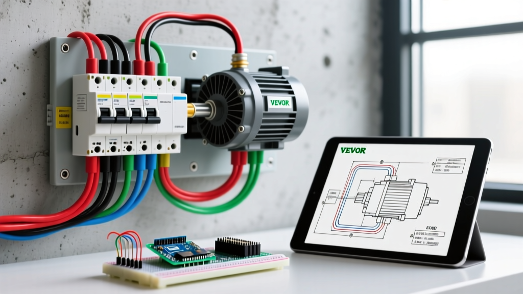
Most VEVOR single-phase, dual-voltage (115V/230V) motors utilize a standardized NEMA terminal block located inside the motor's connection box. When you open the peckerhead (terminal box), you will typically find a block with terminals labeled T1, T2, T3, T4, T5, and T8, alongside the start capacitor wiring. Understanding how these interact is the first step in interpreting the VEVOR electric motor wiring diagram.
Standard NEMA Terminal Configurations
- For 230V Operation (Recommended for 2HP and above): You will connect your Line 1 (Hot) to T1 and T5. Connect Line 2 (Hot) to T4 and T8. Terminals T2 and T3 are tied together and insulated. This configuration places the motor windings in series, halving the amperage draw and reducing voltage drop over long wire runs.
- For 115V Operation: Line 1 connects to T1, T3, and T5. Line 2 (Neutral) connects to T2, T4, and T8. This places the windings in parallel, doubling the amperage draw. Note: Running a 2HP or larger VEVOR motor on 115V requires massive wire gauges and is strongly discouraged for continuous duty.
Pro Tip: If you need to reverse the motor's rotation (e.g., for a specific lathe or blower setup), the VEVOR electric motor wiring diagram will instruct you to swap the connections of T5 and T8. Never swap T1 and T2, as this will not reverse a single-phase induction motor and will cause a dead short.
Panel & Breaker Sizing for VEVOR Motors
Sizing a circuit breaker for an electric motor is fundamentally different from sizing one for standard lighting or receptacle loads. Standard breakers protect the wire; motor branch-circuit short-circuit and ground-fault protection devices must accommodate the massive inrush current (Locked Rotor Amperage, or LRA) that occurs when the motor starts. According to NFPA 70: National Electrical Code (NEC) Article 430.52, the maximum rating for an inverse-time circuit breaker protecting a single-phase motor is 250% of the motor's Full Load Amperage (FLA).
VEVOR Motor Breaker Sizing Matrix (2026 NEC Standards)
| VEVOR Motor Size | Voltage | Approx. FLA | Max Inverse-Time Breaker | Standard Panel Breaker Size |
|---|---|---|---|---|
| 1.5 HP | 230V | 10.0A | 25.0A | 25A (or 30A) |
| 2.0 HP | 230V | 12.0A | 30.0A | 30A Double-Pole |
| 3.0 HP | 230V | 17.0A | 42.5A | 40A or 45A Double-Pole |
| 5.0 HP | 230V | 28.0A | 70.0A | 70A Double-Pole |
Note: Always verify the exact FLA printed on the physical nameplate of your specific VEVOR motor, as manufacturing tolerances and efficiency ratings (e.g., TEFC vs. ODP enclosures) can cause slight variations in amperage.
Wire Gauge Selection & Voltage Drop
NEC Article 430.22 dictates that motor branch circuit conductors must have an ampacity of not less than 125% of the motor's FLA. However, in a practical workshop environment, voltage drop is the silent killer of electric motors. If the voltage at the motor terminals drops below 90% of the rated voltage during startup, the centrifugal switch may fail to disengage the start capacitor, leading to catastrophic failure within minutes.
For a standard VEVOR 2HP (230V, 12A FLA) motor:
- Under 50 feet from panel: 12 AWG Copper THHN is sufficient (Ampacity: 20A+).
- 50 to 100 feet from panel: Upgrade to 10 AWG Copper to mitigate voltage drop during the LRA startup surge.
- Over 100 feet: Use 8 AWG Copper. The initial cost of heavier wire (roughly $0.85/ft for 8 AWG in 2026) is negligible compared to replacing a burnt-out motor winding.
Step-by-Step: Wiring the VEVOR Motor to a Breaker Panel
Follow this sequence to ensure a safe, code-compliant connection from your main or sub-panel to the VEVOR motor terminal box.
- Install the Dedicated Breaker: Turn off the main panel power. Snap the appropriately sized double-pole breaker (e.g., 30A for a 2HP 230V motor) into the panel bus bar. Connect the ground wire to the grounding bar.
- Pull the Conduit and Wire: Run EMT or flexible metallic conduit from the panel to a junction box mounted within 3 feet of the motor. Pull your THHN conductors (two hots, one ground). Do not use a neutral wire for a 230V setup.
- Terminate at the Disconnect/Starter: Wire the line-side of your manual disconnect or magnetic motor starter. Never wire a motor directly to a breaker without a local disconnect switch within sight of the motor (NEC 430.102).
- Connect to the VEVOR Terminal Box: Open the motor peckerhead. Strip the wires 1/2 inch. Using the 230V configuration, tie T2 and T3 together with a wire nut and tape it. Connect Load 1 to T1 and T5. Connect Load 2 to T4 and T8.
- Secure the Ground: Attach the equipment grounding conductor (EGC) to the green grounding screw inside the VEVOR terminal box. Ensure the metal chassis of the motor is bonded.
- Test and Verify: Restore panel power. Engage the local disconnect. The motor should spin up to 3450 RPM within 1.5 seconds. Use a multimeter to verify voltage at the terminals under load; it should read no less than 218V.
The Missing Link: Overload Protection
A common and dangerous mistake DIYers make is assuming the 30A panel breaker will protect the VEVOR motor from burning out. It will not. The breaker protects the wire from catching fire during a short circuit. If the motor becomes mechanically jammed and draws 18A continuously on a 12A FLA rating, the 30A breaker will never trip, but the motor windings will melt.
You must install a Motor Overload Relay or a Magnetic Motor Starter with integrated thermal overloads. In 2026, a reliable entry-level magnetic starter (such as the Eaton C25 Series or Schneider TeSys) costs between $75 and $110. Set the thermal overload dial precisely to the FLA listed on the VEVOR nameplate. This device monitors the heat generated by the current draw and will drop the contactor if the motor overworks, saving your equipment.
Common Wiring Mistakes & Troubleshooting
Even with a correct VEVOR electric motor wiring diagram, field conditions can introduce errors. Refer to the Fluke Motor Troubleshooting Guide for advanced diagnostics, but start with these common VEVOR-specific issues:
Motor Hums but Will Not Spin
This almost always indicates a failure in the starting circuit. The start capacitor (usually a black cylindrical component inside the terminal box) may be dead, or the internal centrifugal switch is stuck open. Disconnect power, safely discharge the capacitor with a 20k-ohm resistor, and test it with a multimeter's capacitance setting. Replace with an identical microfarad (uF) rating.
Breaker Trips Instantly Upon Startup
If the breaker trips before the motor even hums, you have a dead short. Verify that T2 and T3 are not accidentally touching a grounded surface. Ensure you haven't mistakenly wired the motor for 115V while supplying it with 230V, which will instantly fry the windings and trip the panel.
Motor Overheats and Shuts Down on Thermal Overload
Check for excessive voltage drop. If your wire gauge is too small for the distance, the motor will draw higher amperage to compensate for the low voltage, eventually tripping the thermal overload relay. Upgrade your wire gauge or move the transformer/panel closer.
Final Thoughts on Workshop Integration
Successfully wiring a VEVOR motor requires respecting the physics of inductive loads and the strictures of the NEC. By meticulously following the VEVOR electric motor wiring diagram, sizing your panel breakers to handle the locked-rotor amperage, and integrating local thermal overload protection, you ensure your machinery runs reliably for years. Always prioritize 230V configurations for motors 2HP and larger, and never bypass the local disconnect switch requirements for workshop safety.