
Understanding the Wiring Diagram for a Double Pole Switch
When managing high-draw appliances, HVAC systems, or heavy workshop machinery, understanding the exact wiring diagram for a double pole switch is a critical competency for any electrical DIYer or professional. Unlike a standard single-pole switch that interrupts a single 120V hot leg, a double pole switch simultaneously breaks two ungrounded (hot) conductors. This is mandatory for pure 240V loads and highly recommended for Multi-Wire Branch Circuits (MWBC). In this comprehensive panel and breaker guide, we dissect the anatomy of a 240V switching circuit, trace the path from the main breaker panel to the load, and outline the exact National Electrical Code (NEC) parameters governing these installations in 2026.
Core Components and 2026 Hardware Specifications
Before executing any wiring diagram, you must select components rated for the specific amperage and voltage of your circuit. Using undersized hardware is a primary cause of thermal failure and electrical fires.
The Double Pole Breaker
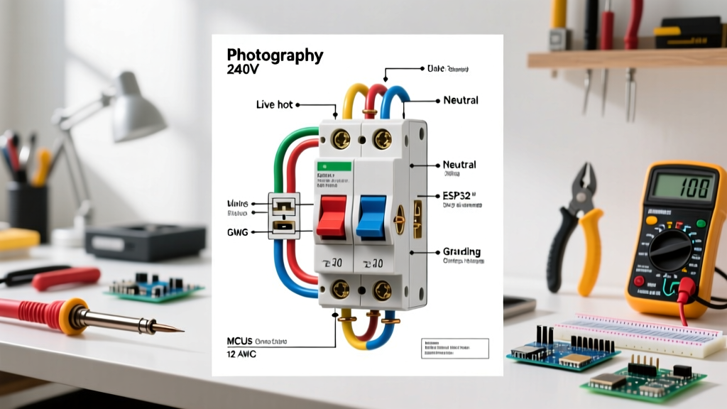
The circuit originates at the panel with a double pole breaker, which spans two adjacent busbar stabs to draw 240V. For a standard 30A water heater or baseboard heater circuit, the Square D Homeline HOM230 (retailing around $18) or the Eaton BR230 ($16) are industry staples. These breakers feature a common trip mechanism; if an overload occurs on one pole, both poles disconnect simultaneously, satisfying NEC Article 240.15.
The Double Pole Switch
For wall-mounted control of 240V resistive loads like baseboard heaters, the Cadet Manufacturing 1721 (22A, 240V, single-pole/double-pole convertible, ~$24) is the gold standard. For heavier inductive loads or workshop disconnects, a heavy-duty toggle like the Hubbell HBL2221A (20A, 125/250V AC, ~$32) provides robust internal arc chutes to handle the higher voltage potential when breaking the circuit.
Conductor Selection
Wire gauge must be matched to the breaker, not the switch. For a 30A circuit, 10 AWG copper is mandatory. In 2026, standard 10/2 NM-B (Non-Metallic Sheathed Cable) costs approximately $0.65 to $0.85 per linear foot. Always verify the insulation rating; NM-B is rated for 90°C, but ampacity calculations must be based on the 60°C column per NEC 310.15(B)(16) for standard residential terminations.
Step-by-Step Wiring Diagram Execution
Follow this precise sequence to wire a double pole switch controlling a pure 240V load (no neutral required).
- Panel Termination: Turn off the main breaker. Strip 3/4 inch of insulation from the black and white conductors of your 10/2 NM-B cable. (Note: Per NEC 200.7(C)(2), the white wire used as a hot leg must be re-identified with black or red phase tape at both ends). Connect the black wire to one pole of the double pole breaker, and the re-identified white wire to the other pole. Land the bare copper ground on the equipment grounding bar.
- Cable Routing and Box Entry: Route the cable to the double-gang or single-gang switch box (depending on switch physical size). Secure the cable with a Romex connector within 8 inches of the box, per NEC 334.30.
- Switch Termination (Line Side): Connect the black line conductor to the top brass terminal on the switch. Connect the re-identified white line conductor to the bottom brass terminal on the same side. Torque the terminal screws to the manufacturer specification (typically 14 to 20 in-lbs using a calibrated torque screwdriver like the Klein Tools 32500 series).
- Switch Termination (Load Side): Run a second 10/2 NM-B cable from the switch to the appliance. Connect the black load wire to the top brass terminal on the opposite side of the switch, and the re-identified white load wire to the bottom brass terminal.
- Grounding Continuity: Splice the bare copper ground wires from the line and load cables together using a wire nut or push-in connector, and run a pigtail to the green grounding screw on the switch yoke and the metal switch box (if applicable).
240V Load Sizing and Wire Gauge Matrix
Properly sizing your breaker, wire, and switch ensures the wiring diagram functions safely under continuous load conditions. The NEC defines a continuous load as one operating for 3 hours or more, requiring the circuit to be derated to 80% of its maximum capacity.
| Breaker Rating | Wire Gauge (Copper) | Max Continuous Load (Watts @ 240V) | Common Application |
|---|---|---|---|
| 15 Amp | 14 AWG | 2,880W | Small window AC units, light duty heaters |
| 20 Amp | 12 AWG | 3,840W | Standard baseboard heaters, window AC |
| 30 Amp | 10 AWG | 5,760W | Electric water heaters, large baseboards |
| 40 Amp | 8 AWG | 7,680W | Electric ranges, cooktops, EVSE Level 2 |
| 50 Amp | 6 AWG | 9,600W | Heavy machinery, subpanels, large EVSE |
Multi-Wire Branch Circuits (MWBC) vs. Pure 240V
A critical distinction in panel wiring is whether your double pole switch is controlling a pure 240V load or a 120/240V Multi-Wire Branch Circuit (MWBC). An MWBC uses two hot wires (black and red) and a shared neutral (white) to supply two separate 120V circuits while saving copper.
If your wiring diagram includes a shared neutral, the double pole switch MUST disconnect all ungrounded conductors simultaneously. Using two separate single-pole switches for an MWBC is a severe NEC violation (Article 210.4) that can lead to a lethal shock hazard if one circuit is turned off while the shared neutral remains energized by the other circuit.
For MWBC applications, ensure the two hot wires are connected to opposite phases (legs) in the breaker panel. This ensures the current on the shared neutral is the difference between the two loads, rather than the sum, preventing neutral conductor overload.
Common Failure Modes and Diagnostic Edge Cases
Even with a perfect wiring diagram, physical installation errors can cause catastrophic failures. Here are the most common edge cases encountered in the field:
- Thermal Creep and Loose Lugs: Aluminum and copper expand at different rates. If terminal screws are not torqued to spec, the heating and cooling cycles of a 240V heater will cause the wire to loosen over time. This increases resistance, leading to localized melting. Always use a torque screwdriver.
- Induced Voltage on Floating Neutrals: When troubleshooting a double pole switch circuit with a digital multimeter, you may read 12V to 50V on a disconnected neutral wire. This is phantom voltage induced by adjacent live conductors. Use a low-impedance voltage tester (LoZ) to confirm the absence of real voltage.
- Breaker-to-Busbar Arcing: If the panel busbar stabs are corroded or the breaker is not fully seated, the high current draw of a 240V load will cause micro-arcing. This manifests as a faint buzzing sound and localized heat on the breaker face. Replace the breaker and inspect the busbar for pitting immediately.
NEC Compliance and Authoritative Safety Standards
All double pole switch installations must adhere to the latest iterations of the National Electrical Code. Specifically, NFPA 70 (National Electrical Code) Article 404 governs the installation of switches, dictating that switches must be accessible and properly grounded. Furthermore, Article 240 mandates that overcurrent protection devices (the breaker) must be rated for the lowest ampacity component in the circuit.
Safety during installation and maintenance is equally paramount. The OSHA Electrical Safety Standards (specifically 29 CFR 1910.333) require strict Lockout/Tagout (LOTO) procedures when working inside breaker panels. Never rely solely on a double pole switch as a disconnecting means for servicing equipment; always trip the breaker, apply a physical lock, and verify zero energy state with a CAT III or CAT IV rated multimeter before touching any conductors. By combining precise adherence to the wiring diagram with rigorous safety protocols, you ensure a resilient, code-compliant 240V circuit that will operate safely for decades.