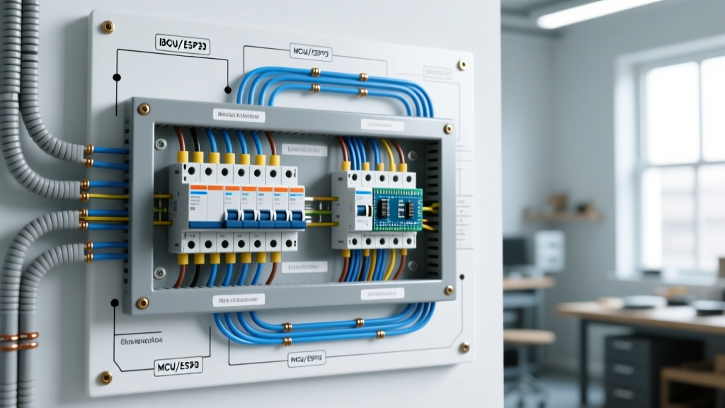

Deconstructing the Standard Electric Panel Wiring Diagram
Planning a residential or light-commercial electrical panel upgrade requires far more than simply mounting a steel enclosure and snapping in breakers. The foundation of a safe, code-compliant installation lies in accurately interpreting the electric panel wiring diagram provided by the manufacturer. Whether you are installing a traditional 200-amp main breaker panel like the Square D Homeline (HOM2448M200PC) or an Eaton BR series subpanel, the wiring diagram dictates bus bar phasing, neutral-to-ground bonding rules, and critical wire bending spaces.
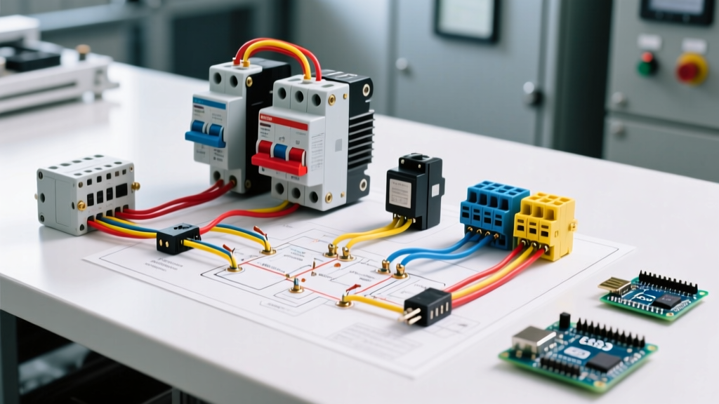
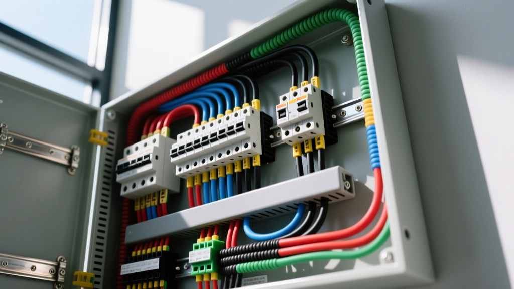
A standard manufacturer diagram is not just a schematic; it is a physical roadmap. It illustrates the A and B phase bus bars, showing how alternating breaker slots connect to opposite 120V legs to balance the 240V load. Misinterpreting this layout during the planning phase often leads to severe phase imbalances, causing the neutral conductor to carry excessive return current, which can overheat the main neutral lug and create a fire hazard.
Main Breaker vs. Main Lug Configurations
Your wiring diagram will fundamentally change based on whether the panel is a Main Breaker or Main Lug configuration. In a Main Breaker setup, the diagram will show the service entrance conductors landing directly on the main breaker lugs, which then feed the bus bars. In a Main Lug panel (often used as a subpanel), the diagram illustrates the main lugs feeding directly to the bus bars, requiring an upstream disconnect. Crucially, the diagram for a subpanel will explicitly show the equipment grounding bus bar isolated from the neutral bus bar, a requirement strictly enforced under NEC Article 250.142.
The 2026 Landscape: Smart Panels and Low-Voltage Integration
As of 2026, the traditional electric panel wiring diagram has evolved. With the widespread adoption of smart electrical panels (such as the SPAN Panel or Leviton Smart Load Center), installation planning now involves both line-voltage and low-voltage schematics. Unlike legacy panels where breakers are purely electromechanical, smart panels utilize solid-state relays and integrated current transformers (CTs).
When planning an installation for a smart panel, the wiring diagram will include dedicated pathways for communication wiring (typically Cat6 or RS-485 shielded cables) that must be routed at least 2 inches away from 120V/240V conductors to prevent electromagnetic interference (EMI). Failing to plan for these low-voltage clearances during the rough-in phase is currently one of the most common causes of smart panel communication dropouts.
Pre-Installation Load Calculation and Breaker Mapping
Before drawing your physical layout, use the panel diagram to map your breaker schedule. Do not simply replicate the old panel's configuration. Modern homes feature significantly higher electrical demands due to EV chargers, heat pumps, and induction cooktops. Perform an NEC Article 220 load calculation to ensure your planned breaker layout does not exceed 80% of the panel's continuous rating.
Below is a reference matrix for standard 2026 residential branch circuits, correlating the wiring diagram's breaker slots to physical wire gauges and termination requirements.
| Circuit Application | Wire Gauge (Copper THHN/THWN-2) | Breaker Size & Type | Typical Termination Torque |
|---|---|---|---|
| General Lighting / Receptacles | 12 AWG | 20A (AFCI/GFCI Dual Function) | 35 - 50 in-lbs |
| Kitchen Small Appliance | 12 AWG | 20A (GFCI) | 35 - 50 in-lbs |
| Electric Dryer | 10 AWG | 30A (2-Pole) | 45 - 60 in-lbs |
| EV Level 2 Charger (40A cont.) | 6 AWG | 50A (2-Pole) | 75 - 90 in-lbs |
| Heat Pump / AC Condenser | 8 AWG | 40A (2-Pole, HACR rated) | 60 - 75 in-lbs |
Physical Layout and Wire Bending Space Compliance
A frequently overlooked aspect of the electric panel wiring diagram is the implied wire bending space. NEC Article 312.6 mandates specific clearances between the breaker terminals and the opposite enclosure wall to accommodate the bending radius of conductors. For a 1/0 AWG service entrance conductor, the code requires a minimum of 5 inches of bending space.
During installation planning, measure the physical depth of your selected enclosure. If you are upgrading to a 200-amp service using 2/0 AWG aluminum (the modern standard due to copper pricing), ensure the panel depth is at least 5.75 inches. If your diagram shows a feed-through lug configuration at the bottom of the bus bars, verify that the enclosure provides adequate vertical clearance below the lugs to bend the heavy gauge wire without kinking the insulation.
Termination Protocols and NEC Torque Mandates
The most critical update in recent NEC cycles, which remains heavily enforced in 2026, is Article 110.14 regarding electrical connections. The electric panel wiring diagram and the panel's interior label will specify exact torque values for every lug. Guessing torque by 'feel' is no longer acceptable and will fail inspection.
Expert Tip: Invest in a calibrated, insulated torque screwdriver. The Wiha 1000V Insulated Torque Screwdriver (Model 28501) or the Klein Tools adjustable torque models are industry standards. For main service lugs, you will need an inch-pound torque wrench, as values for 1/0 and 2/0 AWG aluminum often exceed 200 in-lbs.
When terminating aluminum service entrance conductors, the diagram's notes will typically require the application of an antioxidant compound (such as Noalox) to prevent galvanic corrosion and thermal creep. Thermal creep occurs when aluminum expands and contracts under load, eventually loosening the lug connection if not properly torqued and treated, leading to arcing and panel fires.
Common Diagram Misinterpretations and Failure Modes
Even experienced electricians can fall victim to specific misinterpretations of panel wiring diagrams. Avoid these common installation planning failures:
- Shared Neutrals on AFCI Circuits: Modern diagrams clearly show that Arc Fault Circuit Interrupter (AFCI) breakers require a dedicated, isolated neutral for each circuit. Planning to share a neutral wire between two 120V circuits (a traditional multi-wire branch circuit) on standard single-pole AFCI breakers will result in immediate nuisance tripping. If a MWBC is required, the diagram will direct you to use a specific handle-tied, 2-pole AFCI breaker.
- Double-Tapping Grounds and Neutrals: While some panel diagrams explicitly allow two ground wires under a single ground bus bar screw (if the screw is rated for it), NEC 110.14 strictly prohibits double-tapping neutral conductors under a single lug unless the terminal is specifically identified for the purpose. Plan your neutral bar layout to ensure one wire per screw.
- Ignoring the Bonding Screw: For main service panels, the diagram will show a green bonding screw or strap connecting the neutral bus to the enclosure. For subpanels, this bond must be removed. Failing to plan for the removal of this bond in a subpanel creates a parallel neutral path, energizing the grounding system and presenting a severe shock hazard.
Ensuring Code Compliance and Working Space
Finally, your installation plan must account for the physical environment surrounding the panel. According to OSHA standard 1910.303 and NEC Article 110.26, you must maintain a dedicated working space in front of the panel. For a standard 120/240V residential panel, this requires a clear space 30 inches wide and 36 inches deep, extending from the floor to a height of 6.5 feet.
Furthermore, adherence to the NFPA 70 (National Electrical Code) is non-negotiable for grounding and bonding pathways. Ensure your diagram includes a clear path for the Grounding Electrode Conductor (GEC) to connect to the main grounding bus, separate from the equipment grounding conductors returning from branch circuits. For comprehensive safety guidelines regarding residential electrical systems and arc-fault protection, refer to the Consumer Product Safety Commission (CPSC) electrical safety resources.
By treating the electric panel wiring diagram as a comprehensive planning document rather than a mere post-installation reference, you ensure a safer, more efficient, and fully code-compliant electrical system capable of handling the demands of modern living.