
Understanding the SAE J286 Standard for Trailer Brakes
When referencing an electric brake trailer wiring diagram, it is critical to understand that modern RV and utility trailers rely on the SAE J286 standard for 7-way blade connectors. While many DIYers focus solely on wire colors, the physical pin position on the 7-way plug (often called a Bargman-style connector) is what actually dictates the circuit function. Relying on color alone can lead to catastrophic braking failures, especially when dealing with imported or non-standard harnesses.
As of 2026, advanced brake controllers like the Tekonsha Prodigy P3 and Curt Spectrum utilize proportional deceleration sensors that demand clean, uninterrupted voltage signals. A poorly executed wiring harness will cause voltage drop, resulting in weak braking or controller error codes. This step-by-step walkthrough provides the exact specifications, materials, and routing techniques required to build a professional-grade electric brake circuit.
7-Way Pinout and Wire Gauge Matrix
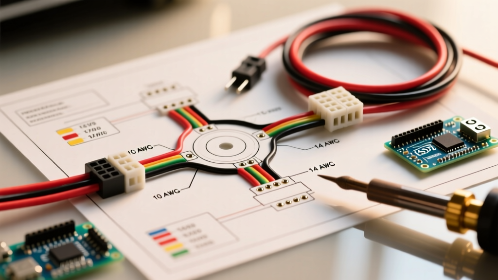
Before cutting any wire, review the standard pinout matrix below. According to the RV Industry Association (RVIA), adherence to these gauge minimums is essential to prevent voltage drop across the typical 20-to-30-foot length of a trailer harness.
| Pin Position (Clock Face) | Function | Standard Wire Color | Minimum Wire Gauge |
|---|---|---|---|
| Center | Chassis Ground | White | 10 AWG |
| 1 o'clock | Tail / Running Lights | Green | 14 AWG |
| 3 o'clock | Right Turn / Stop | Brown | 14 AWG |
| 5 o'clock | Electric Brakes | Blue | 10 AWG |
| 7 o'clock | Left Turn / Stop | Red | 14 AWG |
| 9 o'clock | 12V Aux / Battery Charge | Black | 10 AWG |
| 11 o'clock | Reverse Lights / Aux | Yellow | 14 AWG |
Step-by-Step Electric Brake Wiring Walkthrough
Step 1: Procure the Correct Wire and Connectors
Do not use standard THHN building wire for trailer harnesses. THHN insulation becomes brittle under UV exposure and constant vibration. Instead, purchase 10 AWG TXL (cross-linked polyethylene) stranded wire for the brake (blue) and ground (white) circuits. TXL features a thin, highly abrasion-resistant insulation that withstands engine bay and undercarriage temperatures up to 125°C (257°F).
For terminations, discard standard vinyl crimp connectors. Use 12-10 AWG dual-wall heat shrink butt splices. The inner wall contains a polyamide adhesive that melts during heating, creating a waterproof seal that prevents capillary corrosion from wicking moisture into the copper strands.
Step 2: Route and Loom the Main Harness
Bundle your 10 AWG brake and ground wires with your 14 AWG lighting wires. Encase the entire bundle in a 1/2-inch split corrugated loom. Route the harness along the interior C-channel of the trailer frame, keeping it at least 4 inches away from exhaust components and moving suspension parts. Secure the loom with UV-resistant nylon zip ties every 12 to 14 inches. Never use metal pipe clamps, as vibration will eventually cause them to saw through the loom and short the wires against the steel frame.
Step 3: Terminate the 7-Way Molded Plug
When wiring the 7-way plug (such as the Curt 57672 molded pigtail), always verify the pin positions on the back of the plug casing. Strip exactly 5/16-inch of insulation from your TXL wires. Crimp the heat shrink butt connectors to the pigtail leads, ensuring no copper is exposed outside the heat shrink barrel. Apply heat evenly until the adhesive oozes slightly from both ends of the connector. Coat the entire back of the plug with Permatex Dielectric Grease before inserting it into the mounting bracket to prevent galvanic corrosion between the copper and brass terminals.
Step 4: Wire the Breakaway Switch
The breakaway switch is a critical safety device mandated by the Department of Transportation for trailers over 3,000 lbs GVWR. It must be wired so that if the trailer detaches, the pull-pin is extracted, sending full 12V battery power directly to the electric brakes.
CRITICAL WIRING LOGIC: One wire from the breakaway switch connects to the positive terminal of the trailer's onboard 12V battery. The second wire connects to the blue brake output wire between the 7-way plug and the brake assemblies. Never wire the breakaway switch through the 7-way plug, or it will fail to activate during a complete detachment event.
Use a minimum of 12 AWG wire for the breakaway circuit to handle the initial 15-20 amp inrush current required to lock the brake magnets instantly.
Step 5: Establish a True Chassis Ground
The number one cause of electric brake failure is a poor ground. The white ground wire must terminate directly to the trailer's bare steel frame, not to a painted surface or a rusty bolt. Use a wire brush or flap disc to remove all paint and rust down to bare, shiny metal. Attach a #10 ring terminal using a self-tapping screw and a star lock washer to bite into the metal. Coat the terminal with fluid film or dielectric grease after tightening to prevent future oxidation. For trailers longer than 25 feet, run a dedicated 10 AWG ground wire all the way back to the brake assemblies rather than relying on the trailer's steel frame to carry the return current.
Troubleshooting Matrix: Common Brake Wiring Failures
Even with a perfect electric brake trailer wiring diagram, environmental factors can cause issues. Use this diagnostic matrix to troubleshoot common faults reported by etrailer's technical team and industry experts.
| Symptom | Probable Root Cause | Diagnostic Fix |
|---|---|---|
| Brakes feel weak or 'spongy' despite high controller gain. | Voltage drop due to undersized wire or corroded ground. | Measure voltage at the brake magnet with a multimeter while the manual override is engaged. If below 11.5V, upgrade the ground wire or clean the chassis ground point. |
| Brakes lock up instantly when headlights are turned on. | Short circuit between the running light circuit (green) and brake circuit (blue). | Inspect the 7-way plug for melted pins or moisture ingress. Check the junction box for crossed wires or pinched loom near the axle. |
| Brake controller displays 'S.H.' or 'O.L.' (Overload/Short). | Blue brake wire is shorted to the chassis ground. | Disconnect the blue wire at the 7-way plug. Use a multimeter to test continuity between the blue wire and the trailer frame. Locate and repair the chafed section. |
| Brakes hum or buzz but do not engage fully. | Magnet wear or incorrect brake adjustment. | Remove the hub and inspect the electromagnet face. If the copper windings are visible through the friction face, replace the magnet. Adjust the star wheel until the hub locks, then back off 10 clicks. |
Expert Tips for Long-Term Reliability
To ensure your electric brake system performs flawlessly for years, integrate these maintenance habits into your annual pre-season checklist:
- Annual Magnet Inspection: Electric brake magnets wear down just like brake pads. According to Tekonsha, once the protective epoxy face wears away and the internal copper coil is exposed to the drum, it will short out and destroy your brake controller. Inspect them every 12,000 miles.
- Junction Box Upgrade: If your trailer uses an exposed wire nut junction box, upgrade to a sealed, potting-compound-filled junction box. This completely eliminates moisture intrusion at the most vulnerable split point in the harness.
- Controller Calibration: Whenever you hook up to a new tow vehicle, or if the trailer load changes by more than 20%, you must recalibrate the proportional brake controller. Drive at 25 MPH on a dry, level surface and apply the manual override to set the baseline gain.
By following this exact electric brake trailer wiring diagram methodology and adhering to SAE standards, you eliminate the guesswork and ensure your rig stops safely, predictably, and in compliance with federal towing regulations.