
Understanding the Wiring Diagram for a Alternator
Whether you are restoring a classic muscle car, building a high-draw restomod with electric power steering, or upgrading a marine vessel, understanding the wiring diagram for a alternator is the most critical step in your electrical overhaul. In 2026, the proliferation of high-amperage auxiliary systems—such as electric water pumps, EPS steering racks, and advanced EFI setups—means that stock 60-amp alternators are largely obsolete. Upgrading to a 120A, 150A, or even 200A unit requires precise wiring to prevent voltage drop, parasitic draws, and catastrophic diode failure.
This comprehensive reference guide breaks down the two most common alternator wiring architectures: the traditional 3-wire setup (popularized by the Delco Remy 10SI and 12SI) and the modern 1-wire configuration (common in Denso, Bosch, and aftermarket Powermaster units). We will cover exact terminal pinouts, AWG wire gauge calculations, and real-world failure modes that generic manuals often overlook.
Core Alternator Terminals Explained
Before routing any cables, you must identify the terminals on your specific alternator case. While labeling varies between manufacturers like Bosch, Denso, and Delco Remy, the functional architecture remains consistent.
- B+ (BAT / Output): The main high-amperage output terminal. This connects directly to the battery positive post or the main chassis distribution block.
- Terminal 1 (R / Sense): The remote voltage sense wire. This low-amperage circuit tells the internal voltage regulator what the actual voltage is at the battery or main busbar, allowing it to adjust field current accordingly.
- Terminal 2 (L / IG / F): The ignition or lamp exciter wire. This provides the initial 12V 'wake-up' signal to the voltage regulator when the ignition key is turned to the 'ON' position.
- Case Ground: The alternator chassis must be grounded to the engine block, which in turn must be bonded to the battery negative terminal.
The 3-Wire Alternator Wiring Diagram (Delco 10SI / 12SI Standard)
The 3-wire alternator is the gold standard for classic GM vehicles and is widely used in custom builds due to its superior voltage regulation capabilities. The most iconic example is the Delco 10SI. For a deep dive into classic GM wiring, Mad Enterprises provides the definitive historical schematics for these units.
Step-by-Step 3-Wire Routing
- B+ Routing: Run a heavy-gauge wire (see sizing table below) from the B+ terminal to the battery positive post. Expert Tip: Always install a mega-fuse (rated 10% higher than max alternator output) within 7 inches of the battery positive terminal to protect against a shorted B+ cable.
- Terminal 1 (Sense) Routing: Run a 14 AWG or 16 AWG wire from Terminal 1 to the main battery positive post or the positive side of the starter solenoid. Crucial: Do NOT connect this to the alternator B+ terminal. If you do, the regulator will sense voltage at the alternator, not the battery, leading to undercharging and sulfated batteries.
- Terminal 2 (Exciter) Routing: Run a 16 AWG wire from Terminal 2 to an ignition-switched 12V source. In classic dashboards, this wire is routed through a dash indicator lamp (which acts as a resistor to limit initial current surge) or a 56-ohm resistor in parallel with the lamp.
The 1-Wire Alternator Setup: Simplicity vs. Performance
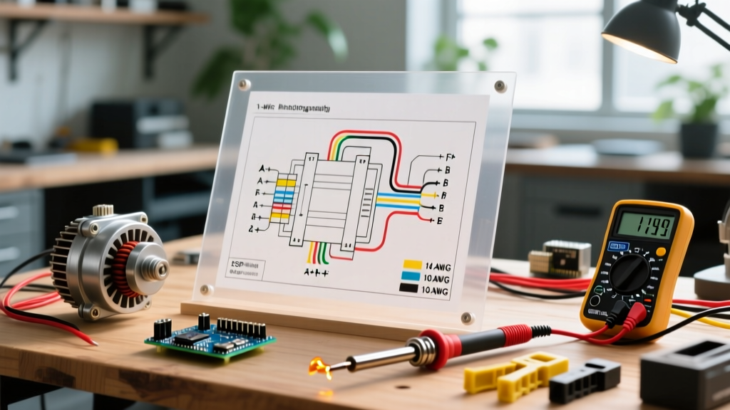
The 1-wire alternator eliminates the sense and exciter wires, relying on a single B+ cable connected to the battery. These units feature an internal jumper that connects the sense circuit directly to the B+ terminal, and a self-exciting voltage regulator that activates only when the alternator reaches a specific RPM threshold (usually between 1,200 and 1,800 engine RPM).
Pros and Cons of 1-Wire Systems
| Feature | 1-Wire Alternator | 3-Wire Alternator |
|---|---|---|
| Installation Complexity | Extremely Low (Plug & Play) | Moderate (Requires dash wiring) |
| Low-RPM Charging | Poor (Requires engine revving to excite) | Excellent (Charges immediately at idle) |
| Voltage Accuracy | Lower (Senses at alternator, not battery) | High (Remote sense compensates for drop) |
| Dash Warning Light | Not Supported (Requires dummy light mod) | Fully Supported |
The Verdict: Use a 1-wire setup only for off-road vehicles, tractors, or simple hot rods where the engine is frequently revved and electrical loads are minimal. For daily drivers, restomods with EFI, or vehicles with high-draw audio systems, the 3-wire diagram is mandatory to prevent voltage drop at the battery.
Wire Gauge Selection & Voltage Drop Calculations
The most common mistake DIYers make when executing a wiring diagram for a alternator is undersizing the B+ output wire. Modern high-output alternators (150A+) will melt a stock 10 AWG wire and cause severe voltage drop. While automotive wire standards (SAE J1128) differ slightly from residential AC codes, referencing standard NFPA NEC ampacity guidelines provides a safe baseline for heavy DC continuous loads.
B+ Wire Sizing Chart (Copper, 12V DC System)
| Alternator Max Output | Cable Length (Under 5 ft) | Cable Length (5 ft to 10 ft) | Cable Length (Over 10 ft) |
|---|---|---|---|
| 60A - 80A | 8 AWG | 6 AWG | 4 AWG |
| 100A - 120A | 4 AWG | 2 AWG | 1/0 AWG |
| 150A - 170A | 2 AWG | 1/0 AWG | 2/0 AWG |
| 200A+ | 1/0 AWG | 2/0 AWG | 4/0 AWG |
Pro-Tip for 2026 Builds: Always use fine-strand, oxygen-free copper (OFC) welding cable or marine-grade tinned copper wire for the B+ run. Avoid Copper Clad Aluminum (CCA) wire sold in cheap automotive kits; CCA has 40% higher resistance and will cause chronic undercharging in high-amp applications.
Real-World Troubleshooting & Edge Cases
Even with a perfect wiring diagram for a alternator, real-world installations encounter edge cases. Here are the most common failure modes and how to diagnose them using a digital multimeter (DMM).
1. The 'Boiling Battery' Syndrome (Sense Wire Misrouting)
Symptom: Battery voltage reads 15.2V+ at the posts, battery is off-gassing, and headlights overdrive and blow out.
Cause: The remote sense wire (Terminal 1) was connected to the alternator B+ terminal instead of the battery. Because the heavy B+ cable experiences a 0.8V drop under load, the alternator only 'sees' 13.6V and ramps up output to 15.2V to compensate, overcharging the battery.
Fix: Reroute the 16 AWG sense wire directly to the battery positive post or the main chassis distribution busbar.
2. Alternator Whine in Audio Systems (Diode Ripple)
Symptom: A high-pitched whine in the car audio system that changes pitch with engine RPM.
Cause: This is rarely a wiring diagram error and more often a failed diode trio inside the alternator, allowing AC ripple to enter the DC system. However, it can also be caused by a poor chassis ground.
Fix: Test for AC voltage at the battery with the engine running. A healthy alternator should show less than 50mV AC. If it reads over 100mV AC, the alternator diodes are fried. If AC voltage is low, install a 1/0 AWG grounding strap directly from the alternator case to the engine block, and from the engine block to the chassis.
3. 1-Wire Alternator Won't Charge at Idle
Symptom: Battery light stays on at idle, but goes off when the engine is revved past 1,500 RPM.
Cause: The internal self-exciter circuit requires a threshold RPM to generate enough residual magnetism to 'wake up' the regulator. This is common with aftermarket 1-wire units paired with aggressive camshafts that have low, rough idle speeds.
Fix: Switch to a 3-wire wiring diagram using an external exciter wire connected to an ignition-switched 12V source, or install an underdrive pulley to increase alternator shaft speed at idle.
Final Verification Steps
After executing your wiring diagram, perform a voltage drop test before starting the engine. Set your DMM to DC Volts. Place the red probe on the alternator B+ terminal and the black probe on the battery positive post. Crank the engine and let it run with loads (headlights, blower motor) turned on. The DMM should read less than 0.2V. If it reads higher, your B+ cable is undersized, your crimps are loose, or you are using inferior CCA wire. Properly sizing your wires and respecting the sense circuit will ensure your charging system operates flawlessly for years to come.