
The Electrical Architecture of 12V DC Winches
Wiring a heavy-duty 12V DC electric winch is not like installing standard automotive accessories. When a 12,000-lb winch like the Champion 12000 or Smittybilt XRC 9.5K Gen2 is under maximum stall load, it can draw upwards of 400 amps. At this amperage, standard automotive relays will instantly melt, and undersized cables will cause severe voltage drop, leading to motor overheating and premature failure. Understanding the correct wiring diagram for winch applications requires a deep dive into high-amperage DC routing, heavy-duty contactors (solenoids), and precise circuit protection.
Unlike permanent magnet motors found in lighter 2,000-lb ATV winches, heavy-duty truck and off-road winches utilize series-wound DC motors. Series-wound motors provide immense starting torque but require a specialized reversing contactor pack to change the drum's direction. This guide breaks down the exact 4-post solenoid wiring schematic, wire gauge matrices, and advanced troubleshooting protocols for modern off-road recovery setups.
Core Components and Specifications
- Series-Wound Motor: Features separate armature and field coil terminals (usually labeled A and B, or 1 and 2).
- 4-Post Contactor (Solenoid Pack):strong> Handles 300A+ continuous current. Common OEM units include the Albright DC88 or Warn-branded equivalents.
- Inline Circuit Breaker: Typically rated between 150A and 250A, installed on the main positive battery feed.
- Control Switch: Low-amperage (14 AWG) rocker or pendant switch that triggers the electromagnetic coils inside the contactor.
Decoding the 4-Post Solenoid Wiring Diagram for Winch Applications
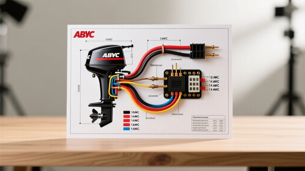
The heart of the winch wiring diagram is the 4-post solenoid pack. This is not a simple on/off relay; it is an H-bridge configuration that reverses the polarity sent to the motor's armature and field coils to dictate spool direction. For authoritative schematics, always cross-reference the Warn Industries official installation manuals, as their contactor logic is the industry benchmark.
The High-Amp Post Configuration
Looking at a standard 4-post contactor with the posts arranged in a square, the high-amperage routing is as follows:
- Top Left Post (Battery Positive Input): Receives the main 12V+ power from the vehicle battery via the inline circuit breaker.
- Top Right Post (Motor Terminal A): Connects to one of the motor's heavy-gauge leads (often the Armature).
- Bottom Left Post (Motor Terminal B): Connects to the motor's second heavy-gauge lead (often the Field Coil).
- Bottom Right Post (Ground / Battery Negative): Routes directly to the vehicle chassis ground or the negative battery terminal.
The Low-Amp Control Circuit Wiring
Each of the four large copper posts also features a small threaded stud for the control wires (usually 14 AWG). These trigger the internal electromagnetic coils.
- Spool In (Power In): When triggered, the contactor bridges the Top Left to Top Right, and Bottom Left to Bottom Right. This sends positive voltage to Terminal A and grounds Terminal B.
- Spool Out (Power Out): When triggered, the contactor bridges Top Left to Bottom Left, and Top Right to Bottom Right. This reverses the polarity, sending positive voltage to Terminal B and grounding Terminal A.
Expert Note: Never swap the Motor A and Motor B cables at the contactor if your winch spools in the wrong direction. Instead, swap the two small control trigger wires at the switch or solenoid studs. Swapping high-amp cables under load can cause severe arcing if the lugs are not perfectly seated.
Step-by-Step High-Amperage Routing and Safety
Executing the wiring diagram for winch systems requires strict adherence to SAE International electrical standards for DC voltage drop and thermal management.
- Disconnect the Battery: Always remove the negative battery terminal before beginning. A dropped wrench across an active 2 AWG winch cable can weld to the chassis and start an electrical fire in seconds.
- Install the Circuit Breaker: Mount a 175A to 250A marine-grade circuit breaker (costing roughly $25-$40) within 18 inches of the positive battery terminal. This protects the main cable run in the event of a dead short.
- Route the 2 AWG Cables: Run the positive and negative 2 AWG pure copper cables away from exhaust manifolds and steering shafts. Use split-loom tubing and zip ties every 12 inches.
- Terminate with Heat Shrink: Use adhesive-lined marine heat shrink on all crimped lugs. Standard vinyl crimps will allow moisture ingress, leading to green copper corrosion and increased resistance.
- Connect the Control Pack: Mount the solenoid pack in a location shielded from direct water spray. While units like the Warn VRX 10-S feature IP68 waterproofing, prolonged submersion can still compromise the low-amp trigger wire seals.
Wire Gauge Sizing and Voltage Drop Matrix
Undersized wiring is the number one cause of winch motor failure. As cable length increases, resistance increases, causing voltage drop. If the voltage at the motor drops below 10.5V under load, the motor will draw excessive amperage to compensate for the lost wattage, rapidly melting the internal windings. The following matrix assumes a pure copper 2 AWG or larger cable setup for a 9,500 to 12,000-lb winch.
| Cable Run Distance (One-Way) | 2 AWG Copper (Max Amps) | 1/0 AWG Copper (Max Amps) | 2/0 AWG Copper (Max Amps) |
|---|---|---|---|
| Under 8 Feet | Up to 350A | Up to 450A | Up to 550A |
| 8 to 14 Feet | Up to 250A | Up to 350A | Up to 450A |
| 14 to 20 Feet | Not Recommended | Up to 250A | Up to 350A |
| Over 20 Feet (e.g., Trailer) | Severe Voltage Drop | Not Recommended | Up to 280A |
Note: For trailer-mounted winches where the cable run exceeds 20 feet, you must install a secondary dedicated battery at the trailer tongue rather than relying on the tow vehicle's alternator and extended cable runs. For more on trailer-specific setups, consult etrailer's comprehensive winch wiring FAQ.
Advanced Troubleshooting: Edge Cases and Failure Modes
Even with a perfect wiring diagram for winch installation, environmental factors and mechanical wear introduce complex failure modes. Here is how to diagnose the most common edge cases.
1. Solenoid Clicking but Drum Will Not Turn
The Symptom: You press the remote, and the solenoid pack emits a loud, rapid clicking sound, but the motor does not spin.
The Diagnosis: This is rarely a bad motor. It is almost always a voltage drop in the control circuit. The electromagnetic coils inside the contactor require a solid 12V to pull the heavy copper contacts together. If your 14 AWG control wires have corroded grounds, or if the vehicle's main battery is depleted below 11.8V, the solenoid will chatter without fully engaging the high-amp posts.
The Fix: Clean the small ground ring terminal on the solenoid pack. If the battery is healthy, bypass the control switch by momentarily jumping 12V directly from the battery positive to the small trigger stud on the solenoid. If the winch engages, your switch or control wiring is faulty.
2. Winch Spools In, But Will Not Spool Out
The Symptom: The winch pulls perfectly but is completely dead in the reverse direction.
The Diagnosis: One half of the H-bridge contactor has failed. Specifically, the internal copper contacts for the "Spool Out" circuit have either pitted from severe arcing or become mechanically stuck. Another possibility is a broken wire inside the pendant remote switch.
The Fix: Test the small trigger studs with a multimeter while pressing the "Out" button. If 12V is present at the stud but the winch doesn't move, the contactor is internally welded or pitted and must be replaced (OEM replacement cost: $45-$90).
3. Parasitic Battery Draw When Idle
The Symptom: The vehicle battery dies after sitting for a few days, even with the winch not in use.
The Diagnosis: Water ingress inside the solenoid pack or the handlebar control switch has created a high-resistance short across the low-amp trigger wires. This keeps one of the electromagnetic coils partially energized, drawing 1 to 3 amps continuously.
The Fix: Disconnect the control plug at the solenoid pack. If the parasitic draw stops, disassemble the control switch, clean it with electrical contact cleaner, and seal the housing with dielectric grease.
The 2026 Upgrade: Solid-State Contactors
For users who frequently winch in extreme conditions (deep water, mud, or heavy snow), the mechanical 4-post solenoid is becoming obsolete. The latest advancement in winch wiring is the Solid-State Contactor. Instead of using physical copper plates that arc, pit, and weld together, solid-state units use high-amperage MOSFETs (Metal-Oxide-Semiconductor Field-Effect Transistors) to route power.
Advantages of Solid-State Wiring:
- Zero Arcing: No physical contacts means no pitting or welding, even under 400A stall loads.
- Instant Reversing: MOSFETs switch in milliseconds, allowing for ultra-precise inching of the drum.
- Waterproof Architecture: The entire circuit board is potted in marine-grade epoxy, completely eliminating the parasitic draw issues caused by water ingress in mechanical packs.
While a solid-state upgrade kit costs between $120 and $180 (compared to $50 for a mechanical replacement), the elimination of catastrophic contactor welding makes it a mandatory upgrade for competitive off-roaders and professional recovery operators. When wiring a solid-state unit, the physical wiring diagram remains identical to the 4-post mechanical layout, but the control wires are often polarity-sensitive, requiring strict attention to the manufacturer's positive and negative trigger designations.