
The Definitive Guide to Tekonsha Brake Controller Wiring
When searching for a reliable wiring diagram for Tekonsha brake controller setups, most generic guides fail to address the critical edge cases that cause trailer sway, blown fuses, or erratic braking. Whether you are installing the flagship Tekonsha Prodigy P3 (Model 90195) or the budget-friendly Primus IQ (Model 90160), the underlying 4-wire harness architecture remains identical. In 2026, with heavier half-ton trucks and multi-axle travel trailers becoming the norm, proper wire gauge selection and circuit breaker sizing are no longer optional—they are critical safety requirements.
This step-by-step walkthrough bypasses the fluff and provides exact measurements, wire routing strategies, and troubleshooting matrices used by professional RV technicians.
The Tekonsha 4-Wire Harness Color Code Matrix
Every Tekonsha proportional and time-delayed controller utilizes a standardized 4-wire pigtail. Misidentifying these wires is the number one cause of installation failure. Below is the exact color-code matrix and its corresponding electrical function.
| Wire Color | Function | Destination | Minimum Wire Gauge |
|---|---|---|---|
| Black | 12V DC Power Input | Vehicle Battery (+) via Circuit Breaker | 10 AWG (12 AWG absolute minimum) |
| White | System Ground | Vehicle Chassis (Bare Metal) | 10 AWG |
| Red | Stoplight Switch Signal | Cold Side of Brake Light Switch | 14 AWG or 16 AWG |
| Blue | Trailer Brake Output | 7-Way RV Connector (Pin 2) | 10 AWG (Crucial for voltage drop) |
Required Tools and 2026 Material Cost Breakdown
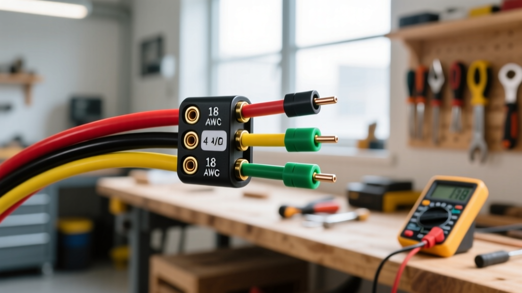
Before pulling panels, ensure you have the correct materials. Using undersized wire on the Blue (output) and Black (power) circuits will result in severe voltage drop, causing the Prodigy P3 to throw an 'SH' (Short) or 'OL' (Overload) code under heavy braking.
- Tekonsha Prodigy P3 Controller: $165 - $190 (Retail)
- 10 AWG Primary Wire (Blue & Black): $1.25 - $1.80 per foot
- 14 AWG Primary Wire (Red): $0.60 per foot
- 30A or 40A Thermal Circuit Breaker: $18 - $25 (Bussmann or Littelfuse)
- Fluke 117 Multimeter (or equivalent): Essential for finding the cold side of the stoplight switch.
- Heat Shrink Butt Connectors (12-10 AWG & 16-14 AWG): $15 per assortment box.
- Ring Terminals & Self-Tapping Screws: For chassis grounding.
Pro-Tip for 2026 Towing Setups: If you are towing a trailer with 3 or more axles (requiring 6+ brake magnets), you MUST upgrade the Black power wire and Blue output wire to 8 AWG and use a 40A circuit breaker. The standard 10 AWG / 30A setup is only rated for up to 4 brake magnets (2 axles).
Step-by-Step Wiring Walkthrough
Step 1: Routing the Power Wire (Black)
Run a continuous length of 10 AWG black wire from the positive terminal of your vehicle's battery to the firewall. Do not connect it to the battery yet. Mount a 30A thermal circuit breaker within 18 inches of the battery positive terminal. This is a strict requirement per NFPA 1192 RV safety standards and prevents catastrophic fires if the wire chafes against the chassis. Connect the black wire to the 'AUX' or 'BAT' terminal on the Tekonsha harness.
Step 2: Establishing a True Chassis Ground (White)
The white wire must ground directly to the vehicle's bare steel frame. Do not ground this to the negative battery terminal (which causes ground loops) or to a painted surface. Locate a factory bolt under the dash connected to the steel firewall or frame rail. Sand away any paint, e-coat, or rust using 80-grit sandpaper. Attach a 10 AWG ring terminal and secure it tightly. A poor ground is responsible for 90% of 'NC' (No Connection) errors on the P3 display.
Step 3: Tapping the Stoplight Switch (Red)
This is the most complex step. The red wire must connect to the cold side of the vehicle's brake light switch. This is the wire that only receives 12V when the brake pedal is physically depressed.
- Locate the brake pedal arm and the stoplight switch plunger.
- Set your multimeter to DC Volts.
- Probe the wires at the switch harness. One wire will have constant 12V (Hot side - often tied to cruise control or ABS). Do not tap this wire.
- The other wire will read 0V until you press the brake pedal, at which point it jumps to 12V. This is your cold side.
- Splice the Tekonsha Red wire into this cold side wire using a heat-shrink butt connector.
Step 4: Routing the Brake Output (Blue)
Run the 10 AWG blue wire from the controller through the firewall, along the frame rail, to the rear 7-way RV connector. Secure it with UV-resistant zip ties every 12 inches, keeping it away from exhaust components and moving suspension parts. Terminate the blue wire at Pin 2 of the 7-way connector.
Standard 7-Way RV Connector Pinout Matrix
When terminating your blue wire at the rear bumper, ensure your 7-way plug is wired to the SAE J286 / RVIA standard. Looking at the face of the vehicle-side receptacle (the female end on the truck), the pinout is as follows:
| Pin Position | Function | Standard Wire Color |
|---|---|---|
| Pin 1 (Top Center) | Ground (White) | White |
| Pin 2 (Top Right) | Electric Brakes | Blue (From Tekonsha) |
| Pin 3 (Bottom Right) | Tail / Running Lights | Brown |
| Pin 4 (Bottom Left) | Left Turn / Stop | Yellow |
| Pin 5 (Bottom Center) | Right Turn / Stop | Green |
| Pin 6 (Top Left) | 12V Auxiliary Power | Black or Red |
| Pin 7 (Center) | Reverse / Aux | Purple |
Common Edge Cases and Troubleshooting
Even with a perfect wiring diagram for Tekonsha brake controller installations, real-world variables can cause issues. Here is how to diagnose the most common post-installation faults:
Fault Code: 'SH' (Short Circuit)
The Problem: The P3 display reads 'SH' when you press the brake pedal. This means the Blue output wire is touching ground somewhere between the controller and the trailer plug, OR the trailer's brake magnets have failed internally and are shorting to the axle.
The Fix: Disconnect the trailer. If the 'SH' code disappears, the fault is in the trailer wiring or magnets. If 'SH' remains with the trailer disconnected, trace the Blue wire under the truck for chafed insulation against the steel frame.
Fault Code: 'OL' (Overload)
The Problem: The controller detects more than 6 brake magnets or a severe short drawing excessive amperage.
The Fix: Verify you only have 2 to 4 brake magnets connected. Check the trailer junction box for moisture ingress causing crossed wires between the Blue (brakes) and Black (12V aux) circuits.
Brakes Lock Up When Turn Signals are Engaged
The Problem: This happens almost exclusively on vehicles with combined turn/stop light circuits (common on European vehicles or specific SUVs) where the Tekonsha Red wire is tapped into the wrong circuit.
The Fix: You must install a Stoplight Isolator Module (like the Tekonsha 201-100) to separate the turn signal voltage from the brake signal voltage before it reaches the controller's Red wire.
Authoritative References and Further Reading
For advanced diagnostics, always refer to manufacturer-specific technical bulletins and industry safety standards. The following resources provide supplemental schematics for specific OEM tow packages:
- Tekonsha Official Technical Support & Wiring Guides - Access model-specific PDF schematics and warranty troubleshooting trees for the P3 and Primus IQ.
- eTrailer Brake Controller Wiring FAQ - An extensive database of vehicle-specific tow package wire locations and adapter harness part numbers for 2015-2026 trucks.
By adhering strictly to this wiring diagram for Tekonsha brake controller systems and respecting wire gauge limitations, you ensure proportional, safe braking that responds dynamically to your tow vehicle's deceleration rates.