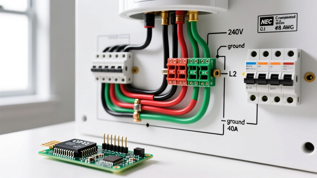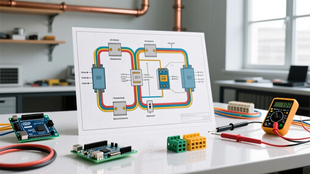

The Residential Motor Blind Spot in Standard Blueprints
When homeowners and DIYers review a standard electrical wiring diagram house blueprint, the focus is overwhelmingly on 15A and 20A branch circuits for lighting and receptacles. However, heavy inductive motor loads—such as submersible well pumps, HVAC compressors, and attic exhaust fans—operate under an entirely different set of physics and electrical codes. Treating a 240V well pump like a standard water heater is a common mistake that leads to nuisance tripping, voltage drop, and premature motor burnout.
As of the 2026 construction cycle, most jurisdictions enforce the 2023 National Electrical Code (NEC). Under the National Fire Protection Association (NFPA) 70 National Electrical Code, motor circuits are governed by Article 430, which introduces unique wire sizing and overcurrent protection rules that completely defy standard residential branch circuit logic. This guide will teach you how to decode your home's motor loads and wire them safely.
Decoding Nameplate Data vs. Standard Branch Circuits
Unlike a resistive load (like a baseboard heater) where you simply divide the wattage by the voltage to find the amperage, AC motors require you to interpret specific manufacturer nameplate data. When tracing an electrical wiring diagram house plan for an HVAC condenser or well pump, look for these four critical acronyms:
| Acronym | Definition | Wiring Application |
|---|---|---|
| FLA | Full Load Amps | The continuous current the motor draws at its rated horsepower. Used to size the thermal overload relay and calculate baseline wire ampacity. |
| LRA | Locked Rotor Amps | The massive inrush current when the motor starts (often 5x to 7x the FLA). Dictates your breaker trip curve and voltage drop calculations. |
| MCA | Minimum Circuit Ampacity | Found on HVAC units. The exact minimum wire ampacity required by the manufacturer, factoring in 125% of the largest motor plus other loads. |
| MOCP | Max Overcurrent Protection | The absolute maximum breaker size allowed to protect the equipment against short circuits without nuisance tripping during LRA inrush. |
The NEC Article 430 Anomaly: Breaker and Wire Sizing
The most confusing aspect of motor wiring for residential electricians is the relationship between wire gauge and breaker size. In standard Article 210 branch circuits, a 30A breaker requires a minimum of 10 AWG copper wire. However, motor circuits flip this rule upside down.
Expert Insight: In a motor circuit, the branch-circuit short-circuit and ground-fault protective device (the breaker) is not responsible for protecting the wire from continuous overcurrent. That job belongs to the motor's internal thermal overload or the external motor controller. The breaker only protects against catastrophic short circuits.
Step-by-Step: Sizing a 1.5 HP Submersible Well Pump
Let us apply NEC Article 430 to a common residential scenario: a 1.5 HP, 240V submersible well pump with a nameplate FLA of 10.0 Amps.
- Calculate Wire Size (NEC 430.22): Conductors must be sized at 125% of the motor FLA.
10.0A × 1.25 = 12.5 Amps.
According to NEC Table 310.16, 12 AWG THHN copper wire (rated for 20A in the 75°C column) is perfectly legal and sufficient. - Calculate Breaker Size (NEC 430.52): For an inverse-time breaker protecting an AC motor, the code allows sizing up to 250% of the FLA to accommodate the LRA startup surge.
10.0A × 2.50 = 25.0 Amps.
You can legally install a 25A double-pole breaker (or a 30A if 25A is unavailable, per code exceptions) to protect a 12 AWG wire. - Install Overload Protection: The pump control box must contain a properly sized thermal overload relay calibrated to the 10.0A FLA to protect the 12 AWG wire from burning up if the pump jams.
Mapping the Control Circuit on Your Diagram
Modern residential motor loads rarely run on simple toggle switches. They rely on low-voltage control circuits to trigger high-voltage contactors. When reviewing the U.S. Department of Energy (DOE) Heat Pump Systems Guide, you will note that inverter-driven compressors and smart thermostats require meticulous control wiring.
HVAC Contactor Integration
A standard 3-ton residential AC condenser utilizes a 24VAC control circuit to energize a 240V contactor coil (such as the Eaton C25DND230). Here is how the wiring flows:
- 24VAC Transformer: Located in the indoor air handler, stepping down 120V to 24V.
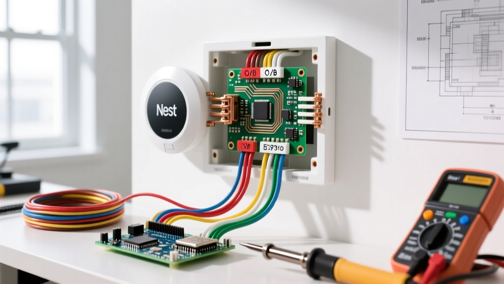
- Thermostat Wiring (18/8 AWG): The Yellow (Y) wire carries the 24V call-for-cooling signal from the thermostat to the air handler, and then out to the condenser.
- Contactor Coil (A1 & A2): The 24V signal completes the circuit across the contactor's magnetic coil. This pulls the high-voltage contacts closed, sending 240V to the compressor and fan motor.
Edge Case Warning: If your electrical wiring diagram house plan shows a long run (over 75 feet) between the air handler and the outdoor condenser, the 18 AWG control wire may suffer from voltage drop, resulting in a weak magnetic pull that causes the contactor to chatter and burn out. Upgrade to 16 AWG or 14 AWG thermostat wire for long runs.
Voltage Drop Calculations for Remote Motors
Motors are highly sensitive to voltage drop. A 5% drop in voltage can result in a 10% drop in torque, causing the motor to run hotter, draw more amps, and fail prematurely. If your house plan places the well pump pressure tank and control box 150 feet from the main panel, you must calculate voltage drop.
The Single-Phase Voltage Drop Formula:
VD = (2 × K × I × D) / CM
- K = 12.9 (Copper resistance constant)
- I = Current (10A FLA)
- D = Distance (150 feet)
- CM = Circular Mils of the wire (6,530 for 12 AWG)
Calculation: (2 × 12.9 × 10 × 150) / 6530 = 5.92 Volts.
On a 240V circuit, a 5.92V drop is roughly 2.4%. This is well within the NEC recommended 3% maximum for branch circuits. However, if the distance was 300 feet, the drop would exceed 4.7%, mandating an upgrade to 10 AWG wire, despite the 12.5A minimum ampacity requirement.
Troubleshooting Common Motor Wiring Failures
When a newly wired motor fails to start or trips immediately, consult this diagnostic matrix before replacing components:
| Symptom | Likely Cause | Corrective Action |
|---|---|---|
| Breaker trips instantly upon startup | Breaker sized too close to FLA; cannot handle LRA inrush. | Verify NEC 430.52 allowances; upgrade to a higher inverse-time breaker (e.g., 25A to 30A) or install a time-delay fuse. |
| Contactor hums but does not pull in | Voltage drop on 24V control wire; coil receiving less than 18VAC. | Measure voltage at A1/A2 under load. Upsize control wire from 18 AWG to 16 AWG. |
| Motor runs hot and trips internal overload | Undersized conductors causing voltage drop at the motor terminals under load. | Measure voltage at the motor contactor while running. If below 228V (on a 240V system), upsize line conductors. |
| Pump cycles rapidly (short-cycling) | Loss of air charge in the pressure tank, not an electrical fault. | Check tank bladder pressure with a tire gauge; recharge to 2 PSI below the pressure switch cut-in setting. |
Final Thoughts on Residential Motor Integration
Successfully integrating heavy motors into your home's electrical system requires looking past standard receptacle wiring rules. By strictly adhering to NEC Article 430 for conductor sizing, respecting the MOCP limits on HVAC nameplates, and properly engineering low-voltage control runs, you ensure your equipment operates efficiently for decades. Always cross-reference your specific equipment installation manual with your local electrical codes, as manufacturer instructions often supersede general code minimums under NEC 110.3(B).