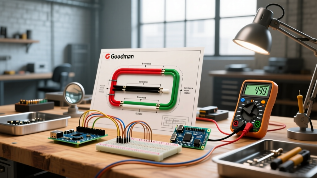

Decoding the Goodman Electric Heat Strip Wiring Diagram
Wiring a Goodman electric heat strip—such as the widely installed HKR or BKR series kits inside ARUF, ASPT, or AVPTC air handlers—is fundamentally different from standard low-voltage thermostat wiring. You are dealing with high-amperage 240V circuits that, if improperly installed, can easily draw enough current to melt wire insulation, destroy control boards, or ignite an electrical fire. According to the National Fire Protection Association (NFPA) NEC guidelines, fixed electric space-heating equipment must strictly adhere to Article 424, while the air handler blower motor falls under Article 440. Understanding the intersection of these two code sections is the cornerstone of a safe, code-compliant installation.
This guide breaks down the exact wiring diagrams for Goodman heat kits, focusing on the critical safety protocols, torque specifications, and wire gauge requirements that separate a professional HVAC installation from a dangerous DIY hazard. Whether you are installing a 5kW HKR05 or a massive 20kW HKR20 kit, the electrical principles and code requirements remain absolute.
NEC Code Compliance: Articles 424 and 440 Explained
When reviewing a Goodman electric heat strip wiring diagram, you will notice two distinct power feeds: the high-voltage 240V supply for the heating elements and the 120V/240V supply for the blower motor and control board. The National Electrical Code (NEC) requires you to calculate the Minimum Circuit Ampacity (MCA) and the Maximum Overcurrent Protection (MOP) based on the combined load.
- NEC Article 424 (Fixed Electric Space-Heating Equipment): Dictates that branch circuits supplying fixed electric space-heating equipment must be sized at 125% of the total heating load.
- NEC Article 440 (Air-Conditioning and Refrigerating Equipment): Covers the blower motor. The MCA calculation requires you to take 125% of the largest motor's full-load amps (FLA) plus 100% of all other loads (the heat strips).
Code Compliance Warning: Never use the heat strip's nominal kilowatt (kW) rating alone to size your breaker. You must use the MCA value printed on the air handler's data plate, which accounts for the blower motor's inductive load and the continuous duty cycle of the heating elements.
Wire Gauge and Breaker Sizing Matrix
Undersized wire paired with an oversized breaker is the most common code violation found in residential heat pump installations. The table below outlines the standard requirements for Goodman HKR series heat strips operating at 240V, single-phase. These values assume copper conductors with 75°C insulation (THHN/THWN) routed in standard NM-B or SER cable, per NEC Table 310.16.
| Heat Kit Model | Nominal kW | Amps (240V) | Typical MCA | MOP (Breaker Size) | Min. Wire Gauge (Cu) |
|---|---|---|---|---|---|
| HKR05 | 4.8 kW | 20.0 A | 26.0 A | 30 A | 10 AWG |
| HKR10 | 9.6 kW | 40.0 A | 51.2 A | 60 A | 6 AWG |
| HKR15 | 14.4 kW | 60.0 A | 76.5 A | 80 A | 4 AWG |
| HKR20 | 19.2 kW | 80.0 A | 101.5 A | 110 A | 2 AWG |
Note: Always verify the exact MCA and MOP on your specific Goodman Manufacturing Air Handler specifications data plate, as blower motor sizes vary by tonnage and will slightly alter the final MCA calculation.
The Danger Zone: M1, M2, and M3 Power Lugs
If you study field failure reports for Goodman air handlers, the most frequent catastrophic failure point is the melting of the M1, M2, and M3 high-voltage terminal lugs. These lugs connect the main 240V branch circuit to the sequencers and heating elements.
Why Do These Lugs Melt?
Melting is rarely caused by the heat strips themselves generating too much ambient heat. Instead, it is caused by high electrical resistance due to improper torque. When a wire is not tightened to the manufacturer's exact specification, the loose connection creates micro-arcing and resistance. According to Joule's Law ($P = I^2R$), a 60-amp circuit with even a fraction of an ohm of resistance will generate massive localized heat, eventually melting the plastic Molex connectors and causing a dead short or fire.
Mandatory Torque Specifications
To comply with NEC 110.14(D), which requires terminations to be torqued to manufacturer specifications, you must use a calibrated inch-pound torque screwdriver. For Goodman HKR/BKR heat kits:
- Main Power Lugs (M1, M2, M3): Torque to 35 to 40 inch-pounds.
- Sequencer Spade Terminals: Ensure a tight, crimped fit. Do not use needle-nose pliers to squeeze them; use a proper ratcheting crimp tool.
- Control Board Screw Terminals: Torque to 12 to 15 inch-pounds. Over-tightening will strip the brass inserts out of the plastic board housing.
Control Circuit Wiring: W1, W2, C, and E
The high-voltage side powers the heat, but the 24V control circuit dictates when the heat turns on. Miswiring the control circuit can cause the heat strips to run continuously, bypassing the thermostat and tripping the high-limit switches.
- W1 (First Stage Heat): Connects from the thermostat's W1 terminal to the air handler control board. The board then sends 24V to the first sequencer coil (H1).
- W2 / AUX (Second Stage Heat): Energizes the second sequencer (H2) for larger heat kits (10kW and above) that stage their elements to prevent massive voltage drops on the home's electrical panel.
- E (Emergency Heat): Bypasses the heat pump defrost board and directly energizes all heat strip sequencers simultaneously. This should only be wired if your thermostat supports true emergency heat staging.
- C (Common): The 24V return path. Never borrow the C-wire from a different transformer; it must originate from the air handler's integrated control module to prevent phase-shorting the transformers.
Safety Devices: Thermal Fuses and Limit Switches
Goodman heat strips are equipped with redundant safety devices to prevent runaway heating. Understanding these is crucial for troubleshooting and code compliance.
Critical Safety Component: The One-Time Thermal Fuse
Located directly on the heating element casing, Goodman utilizes a 150°C (302°F) one-time thermal fuse. If a sequencer's internal contacts weld together in the closed position—a known failure mode in older HVAC systems—the heating elements will receive continuous 240V power, even when the blower is off. The thermal fuse is designed to melt and permanently break the circuit before the elements ignite the surrounding insulation. If this fuse blows, you must replace both the heating element assembly and the sequencers. Never attempt to bypass this fuse with a jumper wire; doing so violates U.S. Department of Energy HVAC installation standards and creates an extreme fire hazard.
Grounding, Bonding, and Disconnect Rules
A common mistake when wiring the Goodman electric heat strip diagram is neglecting the equipment grounding conductor (EGC). The air handler chassis must be bonded to the electrical panel's ground bus. If a 240V heating element shorts to the metal cabinet, the EGC provides the low-impedance path necessary to trip the breaker instantly. Relying on the neutral wire or the mounting straps for grounding is a severe NEC violation.
Furthermore, NEC Article 440 requires a disconnecting means within sight of the air handler. If the air handler is installed in an attic or crawlspace where the main breaker panel is not visible, you must install a local, lockable 240V disconnect switch adjacent to the unit. This ensures that a technician can safely lock out the power before performing maintenance on the blower motor or heat strips.
Troubleshooting Common Installation Failures
If the system is wired but failing to operate correctly, check these specific failure modes before replacing expensive components:
- Breaker Trips Immediately on Call for Heat: Check for a shorted heating element. Use a multimeter to measure resistance across the element terminals. A reading of 0 ohms indicates a dead short. Also, verify the wire gauge is not undersized, causing excessive voltage drop and amperage spikes.
- Blower Runs, But No Heat: Verify 24V is reaching the sequencer coil (H1 to C). If 24V is present but the sequencer doesn't pull in (you should hear a faint click and feel the contacts close), the sequencer coil is open and must be replaced.
- Heat Strips Run Continuously: The sequencer contacts have likely welded closed. Turn off the breaker immediately. Test for continuity across the sequencer's high-voltage contacts with the power off and the coil de-energized. If there is continuity, the sequencer is fused and must be replaced.
Final Thoughts on Code Compliance
Wiring a Goodman electric heat strip requires strict adherence to the manufacturer's diagram and the National Electrical Code. By respecting the MCA/MOP calculations, applying exact torque values to the high-voltage lugs, and ensuring all thermal safety fuses remain intact, you guarantee a system that is not only efficient but fundamentally safe. Always pull the required local permits and have the installation inspected by a certified electrical or mechanical inspector to ensure full compliance and maintain your equipment warranty.