
Mastering the Wiring Diagram for Electric Trailer Brake Controller & Breaker Integration
Integrating an aftermarket brake controller into a vehicle without a factory tow package requires more than just splicing a few wires. It demands a rigorous understanding of power distribution, voltage drop, and overcurrent protection. When you study a standard wiring diagram for electric trailer brake controller setups, the focus is often on the four primary wires. However, from a panel and breaker perspective, the true critical path lies in how you route, protect, and terminate the 12V power supply from the battery or auxiliary fuse block to the controller itself.
In this comprehensive guide, we break down the exact wiring schematics, thermal breaker sizing, and panel integration techniques required for modern proportional controllers like the Tekonsha Prodigy P3 (Part #90195) and the Curt Spectrum (Part #51170). Whether you are wiring a heavy-duty 3-axle gooseneck or a standard 2-axle travel trailer, proper breaker selection is non-negotiable for safety and compliance.
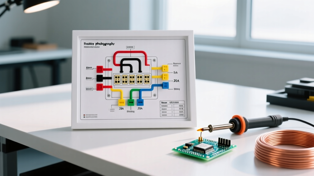
The Core 4-Wire Controller Diagram Explained
Before integrating the circuit into your vehicle's under-hood panel, you must understand the controller's internal architecture. Every standard proportional brake controller relies on four primary connections:
- Black (12V Power): Feeds the internal microprocessor and the PWM (Pulse Width Modulation) output stage. This wire must be protected by a dedicated thermal circuit breaker.
- White (Ground): Must be terminated directly to the vehicle chassis or battery negative. Never share this ground with high-draw accessories like winches or inverters.
- Blue (Brake Output): Carries the modulated DC voltage (0V to 12V) back to the 7-way connector (Pin 2) to energize the trailer's electromagnet brake assemblies.
- Red (Stoplight Switch): Connects to the 'cold' side of the vehicle's brake pedal switch. This signals the controller that the driver is actively braking, waking the PWM circuit.
Panel Integration: Breaker Sizing and Wire Gauge Matrix
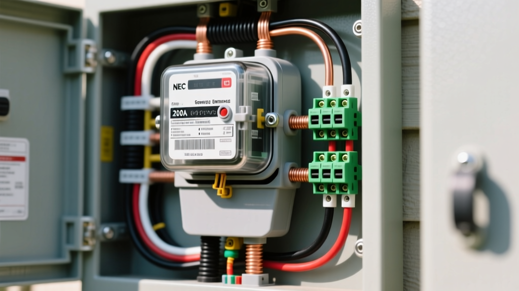
The most common point of failure in aftermarket towing setups is an undersized power wire paired with an improper fuse. Standard automotive blade fuses are not ideal for the high-cyclic, inductive loads generated by trailer brake magnets. Instead, industry best practices dictate the use of a Type P Thermal Circuit Breaker (auto-resetting) mounted within 18 inches of the battery positive terminal or on a dedicated auxiliary bus bar.
Below is the definitive breaker and wire gauge matrix based on the number of trailer axles and the resulting amperage draw.
| Trailer Axles | Max Brake Draw | Required Wire Gauge | Breaker Size & Type | Recommended Breaker Model |
|---|---|---|---|---|
| 1 to 2 Axles | 15A - 20A | 10 AWG Copper | 30A Type P (Auto-Reset) | Bussmann 187300F / Littelfuse MEGA |
| 3 Axles | 25A - 30A | 8 AWG Copper | 40A Type P (Auto-Reset) | Bussmann 187400F |
| 4+ Axles (Heavy Duty) | 35A - 45A | 6 AWG Copper | 50A Manual Reset | Blue Sea Systems 4006 |
Panel Expert Note: For 3+ axle setups, we strongly recommend upgrading to a Manual Reset breaker (like the Blue Sea 4006). If a short occurs in the trailer wiring harness, an auto-reset breaker will continuously cycle, potentially melting the 7-way connector housing before the driver notices the issue. Manual reset breakers force the driver to diagnose the fault before re-energizing the circuit.
The Voltage Drop Equation: Why 12 AWG Wire Fails
Many DIY installers attempt to use 12 AWG wire for the black power feed because it physically fits into the controller's harness plug. This is a critical error. Let us look at the math.
Copper wire has inherent resistance. A standard 12 AWG wire has a resistance of approximately 1.588 ohms per 1,000 feet. If your run from the under-hood panel to the cab-mounted controller and back to the 7-way bumper connector is 25 feet (50 feet round-trip for the circuit), the total resistance is roughly 0.079 ohms.
If you are towing a 2-axle trailer drawing 18 Amps under heavy braking, Ohm's Law (V = I x R) dictates a voltage drop of 1.42 Volts. On a 12V system, a 1.42V drop means your trailer brakes are only receiving 10.58V at maximum panic braking. This results in a 12% loss of braking power, increased stopping distances, and can trigger 'OL' (Overload) or 'SH' (Short) error codes on the controller's LCD screen due to voltage sag at the microprocessor.
The Solution: Always run 10 AWG (or larger) stranded copper wire from the breaker to the controller. 10 AWG drops the resistance to 0.998 ohms/1000ft, cutting the voltage drop down to a safe 0.89V, ensuring the trailer receives maximum clamping force when you need it most. For deeper insights into towing electrical safety standards, refer to the Federal Motor Carrier Safety Administration (FMCSA) regulations on trailer braking requirements.
Step-by-Step Breaker and Panel Routing
When integrating this circuit into your vehicle's electrical panel, follow this exact routing sequence to ensure a clean, serviceable installation:
- Mount the Breaker: Secure the 30A Type P thermal breaker to the firewall or auxiliary fuse block panel. It must be located within 18 inches of the positive battery terminal to protect the entire length of the power feed.
- Run the 10 AWG Power Feed: Route the 10 AWG black wire through the firewall grommet. Use split-loom tubing and secure it with adhesive-backed cable ties every 12 inches to prevent chafing against the dash framework.
- Terminate at the Controller: Crimp a sealed ring terminal or use the specific butt connector provided with the controller harness. Solder-seal heat shrink connectors are mandatory for any splice outside the cab.
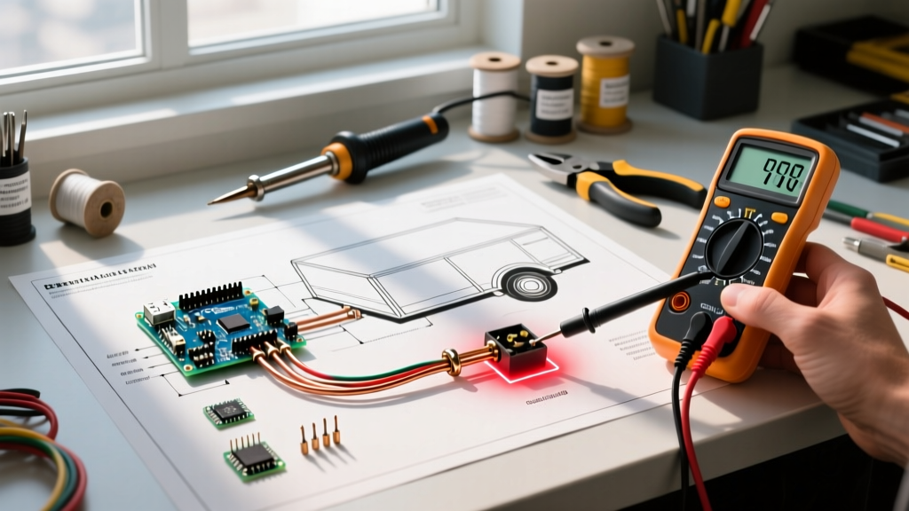
- Wire the Stoplight Circuit: Locate the brake pedal switch. Use a digital multimeter to identify the 'cold' wire (the wire that only shows 12V when the pedal is depressed). Use a proper positap connector rather than a vampire tap, which can sever internal wire strands and cause intermittent red-pin failures.
- Route the Blue Output: Run the blue wire back to the rear 7-way connector. Ensure it is routed along the frame rail, avoiding the exhaust system and moving suspension components.
2026 Controller Nuances: Proportional vs. Time-Delayed
Modern brake controllers have evolved significantly. When wiring newer units, be aware of their specific panel requirements:
- Tekonsha Prodigy P3 (Part #90195): Features an internal inertia sensor. It requires a perfectly level mounting bracket and a clean, unshared ground. A poor ground will cause the LCD to display a flashing red 'SH' code.
- Curt Spectrum (Part #51170): Utilizes a wireless dash-mounted knob and a hidden module. The main module draws a constant micro-amp standby current. If wired to an accessory fuse panel instead of a direct battery/breaker feed, it can drain the vehicle battery over a two-week parking period.
- Redarc Tow-Pro Elite: Requires a highly stable 12V reference. Voltage fluctuations from a failing alternator diode will cause the LED knob to flash a green/red diagnostic code. Ensure your vehicle's charging system is outputting a clean 13.8V - 14.2V before installation.
Troubleshooting Matrix: Breaker & Panel Failures
When the wiring diagram for electric trailer brake controller setups fails, the issue is almost always rooted in the power distribution panel or grounding. Use this matrix to diagnose the fault:
| Symptom | Probable Panel/Breaker Cause | Diagnostic Action |
|---|---|---|
| Controller screen is completely dead | Tripped thermal breaker or blown main fusible link | Check for 12V on the load side of the breaker using a multimeter. |
| Controller powers on, but no output to trailer | Corroded 7-way Pin 2 or broken blue wire at frame routing | Measure voltage at the 7-way connector while an assistant presses the manual override lever. |
| Breaker clicks continuously while towing | Short circuit in trailer wiring or undersized breaker (e.g., 20A on 3 axles) | Disconnect trailer. If clicking stops, the short is in the trailer umbilical or axle magnets. |
| Erratic braking / pulsing sensation | Voltage drop due to 12 AWG power wire or loose ground bus bar | Perform a voltage drop test across the ground wire under maximum manual override. |
Safety Standards and Final Torque Specs
When terminating wires to the circuit breaker studs, torque matters. For standard #10-32 brass studs found on most 30A thermal breakers, the recommended torque is 15 to 20 inch-pounds. Over-torquing will strip the soft brass threads, leading to a high-resistance connection that generates heat and mimics a short circuit, causing the breaker to trip prematurely.
Furthermore, always ensure your trailer's breakaway switch is wired directly to the trailer's onboard battery, but the charging line from the vehicle's 7-way (Pin 4) must also be protected by a separate 40A breaker in the under-hood panel. For comprehensive guidelines on trailer lighting and braking circuits, consult the Curt Manufacturing towing guides and wiring resources.
By treating your brake controller installation as a critical panel integration project rather than a simple plug-and-play accessory, you ensure maximum stopping power, legal compliance, and total peace of mind on the highway.