
The Anatomy of a Modern 48V/52V E-Bike Electrical System
Building a custom electric bicycle in 2026 requires far more than simply bolting a mid-drive motor to a bottom bracket and twisting the throttle. As battery densities have increased and controllers have become more sophisticated, the electric bicycle wiring diagram has evolved into a complex network of high-current power lines and delicate low-voltage signal circuits. Whether you are building a lightweight commuter around a Bafang M600 or a high-torque cargo hauler utilizing a Sabvoton SVMC72150 controller, understanding the precise routing, gauge selection, and connector topology is critical for safety and performance.
At the core of any modern e-bike is the 48V or 52V (13S or 14S lithium-ion) battery pack, managed by a smart Battery Management System (BMS). The BMS communicates with the motor controller to prevent over-discharge and thermal runaway. The controller acts as the brain, converting DC battery power into three-phase AC power for the brushless DC (BLDC) motor, while simultaneously processing 5V logic signals from the pedal assist system (PAS), throttle, hydraulic brake cutoffs, and CAN-bus displays.
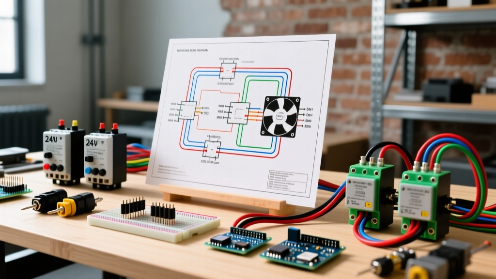
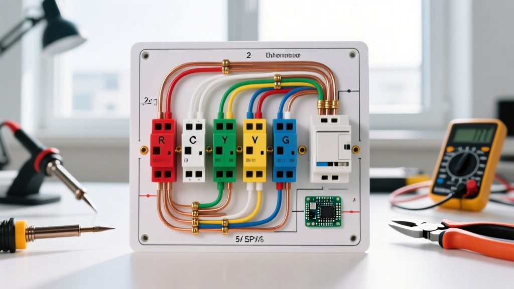
48V Electric Bicycle Wiring Diagram: Logical Component Flow
While visual schematics vary by manufacturer, the logical flow of a standard 48V e-bike wiring harness follows a strict hierarchy. Understanding this flow prevents ground loops and signal interference.
Power Flow: Battery (14S) → BMS Discharge Port → Main Fuse (40A) → XT90-S Anti-Spark Connector → Controller DC Input (Thick Red/Black).
Phase Flow: Controller Phase Output (Thick Blue/Green/Yellow) → Motor Phase Wires.
Signal Flow: Controller 5V/12V Regulator → Higo/Julet Waterproof Pigtails → PAS Sensor, Thumb Throttle, E-Brake Levers, and UART Display.
Feedback Flow: Motor Hall Sensors (5-Pin) → Controller Hall Input (Dictates Commutation Timing).
According to technical resources from Grin Technologies (ebikes.ca), keeping the high-current phase wires physically separated from the low-voltage Hall sensor and signal wires is paramount. Electromagnetic interference (EMI) from the PWM-switching phase wires can induce noise in the Hall signal lines, causing the controller to misread rotor position and resulting in violent motor stuttering or immediate MOSFET failure.
Wire Gauge & Connector Selection Matrix
Selecting the correct wire gauge is not just about preventing melted insulation; it is about minimizing voltage drop under heavy load. When climbing a 15% grade, a 1000W mid-drive can pull 30A continuous from a 48V pack. Using undersized wire will cause the controller's low-voltage cutoff (LVC) to trigger prematurely. The Engineering Toolbox provides standard ampacity charts, but e-bike applications require adjusting for high-vibration environments and bundled wire heat dissipation.
| Application | Wire Gauge (AWG) | Strand Type | Max Continuous Amps | Recommended Connector | Est. Cost (2026) |
|---|---|---|---|---|---|
| Battery to Controller (Main Power) | 8 AWG or 10 AWG | Silicone / Tinned Copper | 40A - 60A | XT90-S (Anti-Spark) | $1.80 / ft |
| Controller to Motor (Phase Wires) | 12 AWG or 14 AWG | Silicone / Tinned Copper | 30A - 50A (Peak 120A) | 4mm Bullet or Higo M510 | $1.10 / ft |
| Hall Sensors & Temp Sensors | 22 AWG to 24 AWG | PVC / Stranded | < 1A | Higo Z510E (5-Pin) | $0.30 / ft |
| Throttle, PAS, E-Brakes | 20 AWG to 22 AWG | PVC / Stranded | < 2A | Higo A210 / SM-2Y | $0.25 / ft |
| Lighting & Accessories (12V/48V) | 18 AWG | PVC / Stranded | 5A - 10A | Higo B210 or JST-SM | $0.45 / ft |
High-Current Power Lines: The Case for XT90-S
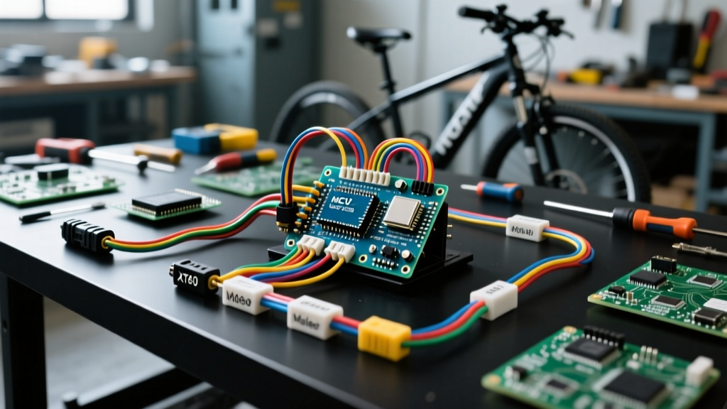
For the main battery-to-controller connection, the XT90-S is the undisputed industry standard for builds exceeding 1500W. Unlike standard XT60 or XT90 connectors, the XT90-S features a built-in spark suppression resistor on one of the male pins. When you plug in a 52V battery to a controller with large capacitive loads, the initial inrush current can exceed 100A for a fraction of a second. Without an anti-spark resistor, this arc will pit the brass contacts, increasing resistance and eventually melting the connector housing. The XT90-S pre-charges the controller capacitors safely, extending the lifespan of your power contacts.
Motor Phase & Hall Sensor Lines
Phase wires carry the raw, PWM-chopped AC current to the motor windings. Because these wires experience severe skin effect and high-frequency heating, you must use ultra-flexible, high-strand-count silicone wire. Keep phase wires as short as physically possible—ideally under 12 inches. Excessive phase wire length increases inductance, which can cause voltage spikes that exceed the 100V rating of your controller's MOSFETs, leading to catastrophic short circuits.
Step-by-Step Wiring Sequence (Preventing Controller Death)
The most common mistake made by novice e-bike builders is connecting the battery before the motor. This sequence is a guaranteed way to destroy a brushless motor controller. Follow this exact order:
- Connect Motor Phase Wires: Mate the thick Yellow, Green, and Blue wires from the controller to the corresponding motor wires. Ensure bullet connectors are fully seated and insulated with heat shrink.
- Connect Hall Sensors: Plug in the 5-pin Higo connector. This provides the controller with the 5V logic ground and signal lines required to read the rotor position.
- Connect Peripherals: Plug in the PAS sensor, throttle, brake cutoffs, and display. Ensure no bare 5V wires are touching the frame or ground.
- Power On (The Final Step): Only after all motor and signal connections are secure should you plug in the main XT90-S battery connector. The controller will initialize, read the Hall sensors, and calibrate the throttle baseline.
Common Wiring Failure Modes & Troubleshooting
Even with a perfect electric bicycle wiring diagram, real-world vibrations and moisture ingress cause specific failure modes. The technical community at Endless Sphere frequently documents these edge cases:
- Hall Sensor 5V Short: If the 5V Hall signal wire chafes against the metal frame or a phase wire, it shorts the controller's internal 5V voltage regulator. Symptoms include a completely dead display, no throttle response, and the motor refusing to spin. Fix: Isolate the harness and test the 5V pin with a multimeter.
- Phase Wire Meltdown at the Connector: Often caused by using standard 3.5mm bullet connectors on a 40A+ system. The contact area is too small, creating a high-resistance bottleneck. Fix: Upgrade to 4.0mm or 5.0mm gold-plated bullets and solder directly to the phase wires.
- PAS Sensor Dropout: The pedal assist sensor relies on a precise 1-3mm air gap between the magnetic disc and the Hall pickup. If the bottom bracket loosens, the gap widens, and the PAS signal drops out, leaving you with throttle-only operation. Fix: Apply blue Loctite to the crank arm bolts and verify the gap with a feeler gauge.
- BMS CAN-Bus Communication Errors: Modern smart BMS units (like the Daly or JBD 2026 models) communicate via CAN-bus or RS485. If the twisted pair wires are routed parallel to phase wires, EMI will corrupt the data packets, causing the BMS to falsely trigger a safety cutoff. Fix: Cross signal wires at 90-degree angles to phase wires, never run them parallel.
Voltage Drop Calculations for Long-Tail Cargo E-Bikes
In 2026, long-tail cargo e-bikes (like custom builds mimicking the Surly Big Dummy or RadWagon) are incredibly popular for urban logistics. However, the battery is often mounted on the rear rack, requiring 4 to 5 feet of wiring to reach a front-mounted or mid-drive controller. This extra length introduces significant voltage drop.
Using the formula Voltage Drop = 2 × Length × Current × Resistance per foot, we can calculate the loss. For 10 AWG wire (0.00102 ohms/ft), running 4 feet (8 feet round trip) at 40A continuous draw results in a 0.32V drop. While 0.32V seems negligible, if you drop to 12 AWG wire (0.00162 ohms/ft), the jump to 15 AWG under peak 80A surges will trigger the controller's transient protection. For long-tail builds, always over-spec the main power trunk line to 8 AWG and utilize a secondary fuse block near the controller for accessory distribution.
Waterproofing & Cable Management Best Practices
An e-bike is a marine environment in the making. Road spray, puddle submersion, and condensation will find any gap in your wiring harness. To ensure longevity:
- Dielectric Grease: Apply a dab of marine-grade dielectric grease inside all Higo and Julet waterproof connectors before mating them. This prevents galvanic corrosion between the copper and brass pins.
- Adhesive-Lined Heat Shrink: Never use standard PVC heat shrink on battery-to-controller joints. Use 3:1 ratio polyolefin heat shrink with an inner wall of meltable adhesive. When heated, the adhesive oozes out the ends, creating a 100% waterproof, vibration-proof seal.
- Drip Loops: When routing wires into the controller bag or frame bag, always create a 'drip loop'—a U-shape in the cable that hangs below the entry point. This ensures water runs off the bottom of the loop rather than wicking down the wire directly into the connector housing.
- Split Loom and Frame Tape: Protect wires from chain-slap and sharp frame edges using nylon split loom. Secure the loom to the frame using fiberglass-reinforced tape rather than standard zip ties, which can crack in sub-zero winter temperatures.
By adhering to this comprehensive electric bicycle wiring diagram and respecting the physics of high-current DC systems, your 2026 e-bike build will deliver reliable, efficient, and safe power for thousands of miles of riding.