
Mastering the Language of Motor Control
Interpreting wiring electric motor diagrams is a foundational skill for any electrical technician, DIY enthusiast, or maintenance engineer. Unlike standard residential wiring, motor circuits involve complex starting mechanisms, dual-voltage configurations, and strict adherence to the National Electrical Code (NEC). A misread diagram doesn't just mean a tripped breaker; it can result in catastrophic winding failure, melted insulation, or severe arc flash hazards.
In this comprehensive tutorial, we will decode the symbology used in modern motor schematics, walk through the exact terminal connections for single-phase and three-phase induction motors, and explore the 2026 best practices for integrating Variable Frequency Drives (VFDs) with high-efficiency IE4 and IE5 premium motors.
Decoding Symbology: NEMA vs. IEC Standards
Before touching a wire, you must identify which standard your motor adheres to. In North America, the National Electrical Manufacturers Association (NEMA) dictates standard terminal markings and schematic symbols. Conversely, European and many global imports follow the International Electrotechnical Commission (IEC) standards.
Key Schematic Symbols to Recognize
- Contactors and Relays: Represented by a box with a coil symbol. Auxiliary contacts are shown with a dashed line linking them to the main coil.
- Overload Relays (OL): Depicted as a box with a bimetallic strip or thermal symbol, placed in series with the motor line.
- Centrifugal Switch: Found only in single-phase diagrams, usually drawn as a switch that opens when the motor reaches 75% of synchronous speed.
- Capacitors: Parallel lines (start capacitors) or parallel lines with one curved edge (run capacitors).
Single-Phase Motor Wiring: Split-Phase and Capacitor-Start
Single-phase motors are ubiquitous in residential HVAC systems, air compressors, and workshop machinery. Because single-phase power lacks a rotating magnetic field, these motors require auxiliary windings and starting mechanisms to generate initial torque.
Standard Terminal Identification
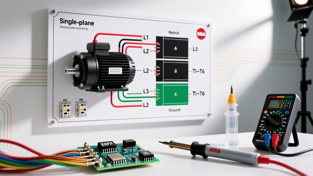
According to NEMA standards, a standard single-phase dual-voltage motor will feature terminals labeled L1, L2, T4, T5, T8, and sometimes P1, P2 for thermal protectors.
- L1 and L2: The main power line connections.
- T4 and T5: The start winding leads.
- T8: The common connection point for the start winding and the centrifugal switch.
Wiring for High vs. Low Voltage (115V vs. 230V)
Most industrial single-phase motors are dual-voltage. The internal main windings are wired in series for high voltage (230V) and in parallel for low voltage (115V).
Expert Insight: When wiring a 230V circuit, the start winding remains in parallel with one of the main windings. Never place the start winding in series across the full 230V line, or the start capacitor will explode within seconds of energization.
Three-Phase Dual Voltage Wiring: The 9-Lead Matrix
Three-phase induction motors are the workhorses of industrial manufacturing. The most common configuration you will encounter in wiring electric motor diagrams is the 9-lead dual-voltage wye (star) connected motor. This allows the motor to operate on either 230V or 460V three-phase power.
The 9-Lead Connection Table
Below is the definitive connection matrix for a standard 9-lead NEMA wye-connected motor. Always verify the nameplate diagram, as delta-connected 9-lead motors use a completely different internal topology.
| Terminal Lead | High Voltage (460V) Series Wye | Low Voltage (230V) Parallel Wye |
|---|---|---|
| L1 (Line 1) | Connect to T1 | Connect to T1 and T7 |
| L2 (Line 2) | Connect to T2 | Connect to T2 and T8 |
| L3 (Line 3) | Connect to T3 | Connect to T3 and T9 |
| Neutral/Star Point 1 | Tie T4, T7, and T8 together | Tie T4, T5, and T6 together |
| Neutral/Star Point 2 | Tie T5 and T9 together | Tie T7, T8, and T9 to Lines |
| Neutral/Star Point 3 | Tie T6 and T4 together | (Handled in Line connections) |
Sizing Contactors and Overload Protection
Reading the diagram is only half the battle; sizing the components correctly is mandated by NEPA 70 (NEC) Article 430. You cannot simply size the breaker based on the motor's Full Load Amps (FLA).
The 125% Rule for Continuous Duty
For continuous duty motors (running for 3 hours or more), the branch circuit conductors must be sized at 125% of the motor nameplate FLA. However, the inverse-time circuit breaker (standard breaker) can be sized up to 250% of the FLA to accommodate the massive inrush current (Locked Rotor Amps) during startup.
Example: A 10 HP, 460V motor has a nameplate FLA of 14A.
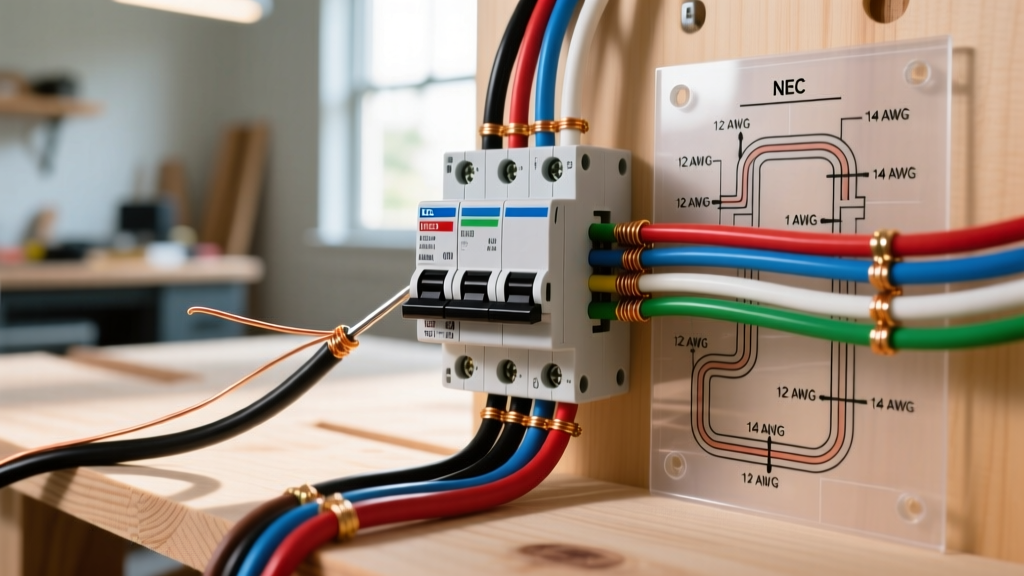
- Wire Sizing: 14A x 1.25 = 17.5A. You must use a minimum of 12 AWG THHN copper wire (rated for 20A).
- Overload Relay Setting: Set precisely to 14A (or 115% of FLA if the motor has a 1.15 service factor).
- Circuit Breaker: 14A x 2.5 = 35A. A standard 35A breaker is permitted, though a 30A breaker is often used if it holds during startup.
Modern Integration: VFD Wiring Best Practices for 2026
As the U.S. Department of Energy pushes for higher industrial efficiency, Variable Frequency Drives (VFDs) are now standard on most new IE4 and IE5 premium efficiency motors. Wiring a VFD requires a departure from traditional across-the-line diagrams.
Critical VFD Wiring Rules
- Never put a contactor between the VFD and the motor. Opening a contactor while the VFD is outputting power will cause a massive voltage spike, instantly destroying the VFD's IGBTs (Insulated-Gate Bipolar Transistors).
- Use Symmetrical Shielded Cable: Standard THHN in conduit causes high-frequency electromagnetic interference (EMI). Use specialized VFD cable with a continuous corrugated aluminum shield.
- Grounding Rings: Modern PWM (Pulse Width Modulation) drives induce shaft voltages that discharge through motor bearings, causing fluting. Always install an AEGIS-style shaft grounding ring on motors larger than 5 HP when driven by a VFD.
Real-World Troubleshooting Edge Cases
Even with perfect wiring electric motor diagrams, field conditions introduce variables. Here are three common failure modes and how to diagnose them:
1. Motor Hums but Will Not Start
Cause: In single-phase motors, this almost always indicates a failed start capacitor or a stuck centrifugal switch. The start winding is not energizing, meaning no rotating magnetic field is generated.
Fix: Discharge the capacitor safely using a 20k-ohm 5-watt resistor. Test with a multimeter's capacitance setting. If the reading is more than 10% below the microfarad (µF) rating printed on the can, replace it.
2. Motor Runs in Reverse
Cause: Incorrect phase sequence (three-phase) or incorrect start winding polarity (single-phase).
Fix: For three-phase, simply swap any two line leads (e.g., swap L1 and L2). For single-phase, swap the connections of the start winding leads (T5 and T8) relative to the main winding. Never swap the main power leads L1 and L2 to reverse a single-phase motor; it will not work.
3. Nuisance Tripping on Overload Relay
Cause: Voltage unbalance or loose terminal connections. A mere 2% voltage unbalance across three phases can cause a 15% increase in motor winding temperature, triggering the thermal overload.
Fix: Measure line-to-line voltage at the contactor load side while the motor is running. If the variance exceeds 1%, contact the utility or investigate upstream transformer taps. Check all terminal lugs with a torque screwdriver to manufacturer specifications.
Final Safety Directives
Always perform a Lockout/Tagout (LOTO) procedure before opening any motor connection box. Use a CAT III or CAT IV rated non-contact voltage tester to verify zero energy state. Remember that capacitors can retain lethal charges long after power is removed, and VFD DC bus capacitors can hold 600V+ DC for up to 15 minutes after disconnect. Always measure the DC bus voltage before touching internal VFD terminals.