
Introduction to Century Motor Wiring Architecture
Wiring an industrial or HVAC motor requires precision, an understanding of electromagnetic principles, and strict adherence to safety codes. When working with a wiring diagram for Century electric motor configurations, technicians must account for the brand's rich legacy. Now fully integrated into the Regal Rexnord portfolio as of 2026, Century motors remain the gold standard for pool pumps, HVAC blowers, and air compressors. Whether you are wiring a classic single-phase C-Face model like the H1036 or a heavy-duty B2858 pool pump motor, the fundamental terminal designations follow standardized NEMA (National Electrical Manufacturers Association) protocols.
This comprehensive tutorial will guide you through decoding the nameplate, configuring dual-voltage single-phase connections, integrating start/run capacitors, and troubleshooting common failure modes. Always cross-reference your physical motor's schematic with the official Regal Rexnord Century technical documentation before applying power.
Decoding the Nameplate: Your Primary Wiring Diagram
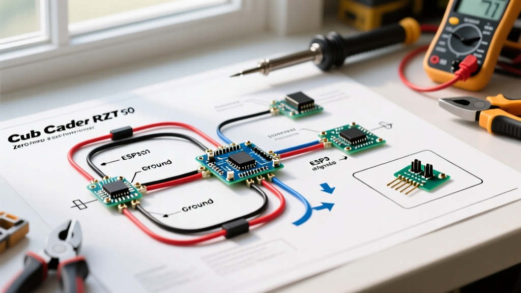
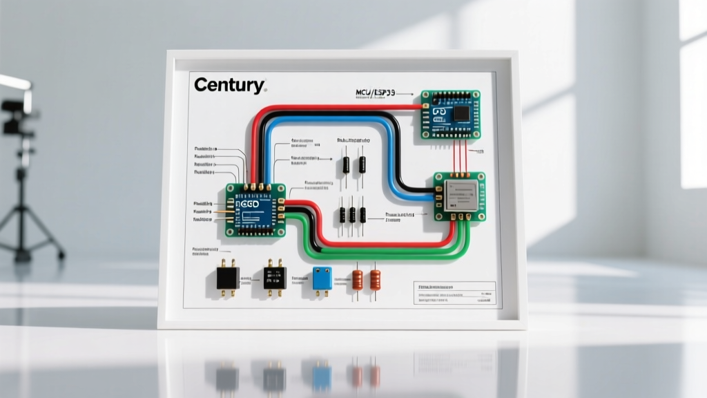
The physical wiring diagram for a Century electric motor is almost always printed on the motor's nameplate or tucked inside the terminal box cover. Before stripping any wires, you must extract critical operational parameters from this plate. Ignoring the Service Factor (SF) or Full Load Amps (FLA) can lead to immediate thermal overload trips or catastrophic winding failure.
| Parameter | Definition | Typical Century Value (e.g., B2858) |
|---|---|---|
| HP (Horsepower) | Mechanical output capacity. | 1.5 HP |
| Volts | Acceptable input voltage (Dual Voltage). | 115/230V |
| FLA (Full Load Amps) | Current draw at rated HP and voltage. | 18.6A (115V) / 9.3A (230V) |
| SF (Service Factor) | Multiplier indicating safe overload capacity. | 1.10 (Allows 10% continuous overload) |
| RPM | Synchronous speed at 60Hz under full load. | 3450 RPM (2-Pole) |
Step-by-Step Tutorial: Single-Phase Dual Voltage Wiring
Most residential and light-commercial Century motors are single-phase, dual-voltage (115V/230V). The wiring diagram for these Century electric motor variants relies on a standardized 8-terminal system (T1 through T8) for the main run windings, plus auxiliary terminals for thermal protection and capacitors.
High Voltage (230V) vs. Low Voltage (115V) Configuration
The fundamental rule of dual-voltage wiring is that in a 230V configuration, the two main run windings are wired in series. In a 115V configuration, they are wired in parallel. Below is the standard NEMA terminal connection matrix used across the Century lineup.
| Voltage | Line 1 (Hot) | Line 2 (Hot/Neutral) | Wire Nut Jumper Connections |
|---|---|---|---|
| 230V (High) | T1, T4, T5 | T2, T3, T8 | T2 & T3; T4 & T5 (Internal series link) |
| 115V (Low) | T1, T3, T8 | T2, T4, T5 | T1 & T3 & T8 (Hot); T2 & T4 & T5 (Neutral) |
Pro-Tip for 2026 Installations: When wiring a Century motor for 230V, always use a 2-pole breaker and 12 AWG THHN copper wire for circuits up to 20A. Ensure your wire stripping length is exactly 1/2 inch to prevent exposed copper from arcing against the terminal box housing, and torque the terminal screws to 15 in-lbs to prevent thermal loosening over time.
Execution Steps for 230V Wiring
- Verify Power Off: Use a CAT III multimeter to confirm 0V at the disconnect switch.
- Identify Terminals: Locate T1 through T8 on the Century motor's terminal board. Clean any oxidation with a fiberglass scratch pen.
- Set Jumpers: Connect T4 to T5 using the provided brass jumper or a short piece of 12 AWG wire. Connect T2 to T3.
- Connect Line Voltage: Attach Line 1 (Black) to the T1, T4, T5 node. Attach Line 2 (Red/White) to the T2, T3, T8 node.
- Grounding: Connect the bare copper or green ground wire to the designated green grounding screw on the motor chassis. NEC Article 430 mandates this equipment grounding conductor must be sized per Table 250.122.
Integrating Start and Run Capacitors
Single-phase Century motors require a phase shift to generate starting torque. This is achieved via capacitors. The wiring diagram for a Century electric motor with a capacitor-start/capacitor-run (CSCR) design will include terminals labeled Z1, Z2, and sometimes Z3.
- Start Capacitor (CBB61/CBB65): Typically rated between 100-300 µF. Wired in series with the centrifugal switch and the start winding. It is only in the circuit for the first 1-2 seconds of startup.
- Run Capacitor: Typically rated between 5-50 µF. Wired directly across the start and run windings (often Z1 to T2). It remains in the circuit continuously to improve power factor and efficiency.
Failure Mode Alert: If a Century motor hums but fails to rotate, the centrifugal switch may be stuck open, or the start capacitor has failed (indicated by a bulged top or leaking dielectric fluid). Replacement CBB65 capacitors cost between $14 and $28 in 2026. Always discharge capacitors with a 20k-ohm, 5-watt resistor before handling.
Common Wiring Mistakes and Edge-Case Failures
Even experienced technicians make errors when interpreting complex motor schematics. Review these common failure modes specific to Century motor installations:
1. Thermal Overload Nuisance Tripping
Many Century models feature an internal thermal overload protector (terminals P1 and P2). If you wire the motor for 115V but the facility voltage sags to 105V under load, the FLA will spike, tripping the P1/P2 disc. Solution: Do not bypass the P1/P2 jumper. Instead, reconfigure the motor to 230V if the facility supports it, which halves the amperage draw and eliminates voltage-drop-induced tripping.
2. Reversing Motor Rotation Incorrectly
To reverse the rotation of a single-phase Century motor, you must swap the start winding leads relative to the run winding. Do not swap Line 1 and Line 2. Swapping the main power lines will not change rotation on a single-phase motor; it will only change rotation on a 3-phase motor. Consult the schematic for the specific Z-leads (usually Z5 and Z8) designated for reversal.
3. VFD Incompatibility with Standard PSC Motors
If you are attempting to wire a standard Century Permanent Split Capacitor (PSC) motor to a Variable Frequency Drive (VFD) for speed control, stop. Standard PSC motors will overheat and fail at low frequencies due to inadequate shaft-mounted fan cooling. You must upgrade to a Century VGreen ECM (Electronically Commutated Motor) which features an integrated inverter and specialized harness connectors rather than raw terminal screws.
Safety Protocols and NEC Compliance
Motor wiring is strictly governed by the National Electrical Code (NEC). According to NFPA 70 (NEC) Article 430, motor branch circuits require specific overcurrent protection. A Century motor drawing 9.3A at 230V requires a branch circuit rated at 125% of the FLA (11.6A). Therefore, a 15A breaker is the minimum, but a 20A breaker with 12 AWG wire is the industry standard for longevity. Furthermore, NEMA MG 1 Standards dictate that the terminal box must remain closed during operation to maintain the motor's IP (Ingress Protection) rating and prevent accidental contact with energized parts.
Frequently Asked Questions
Can I use a 3-phase wiring diagram for a Century single-phase motor?
No. Single-phase and 3-phase motors have entirely different internal winding architectures. A 3-phase diagram relies on L1, L2, L3 and T1-T9 configurations. Attempting to apply 3-phase power to a single-phase Century motor will result in immediate catastrophic winding failure and poses a severe fire hazard.
What do the yellow and orange wires do on my Century HVAC blower motor?
In multi-speed Century HVAC blower motors (like the O.E.M. replacement series), color-coded leads dictate speed taps. Typically, Black is High, Blue is Medium, Red is Low, and Yellow/Orange are unused extra speeds. Unused speed taps must be individually insulated and tied back; they carry induced voltages that can shock you or short against the chassis if left bare.
How do I test the windings before wiring?
Set your multimeter to Ohms (Ω). Measure across T1 and T4 (Run Winding 1) and T2 and T3 (Run Winding 2). You should read a low, balanced resistance (e.g., 2.5 to 5.0 ohms). Measure from any T-terminal to the motor chassis; the reading must be infinite (OL). Any finite reading to ground indicates a shorted winding, and the motor must be replaced.