
Decoding the Wiring Diagram for Shed Subpanels
Drafting a reliable wiring diagram for shed electrical systems requires more than just mapping out outlets and light switches. The true backbone of any outbuilding electrical project lies in precise wire gauge selection, strict adherence to National Electrical Code (NEC) color coding, and managing voltage drop over long trench runs. In 2026, with copper prices remaining volatile and local inspectors enforcing the latest NEC 2023/2026 cycle updates, guessing your wire size or miswiring a subpanel neutral bar will result in failed inspections, melted insulation, or severe shock hazards.
This reference guide bridges the gap between a basic schematic and the physical execution of a shed subpanel. We will break down the exact American Wire Gauge (AWG) requirements based on distance, demystify the NEC 310.12 color code mandates, and highlight the critical isolation rules that separate a safe shed subpanel from a dangerous one.
Anatomy of a Compliant Shed Wiring Diagram
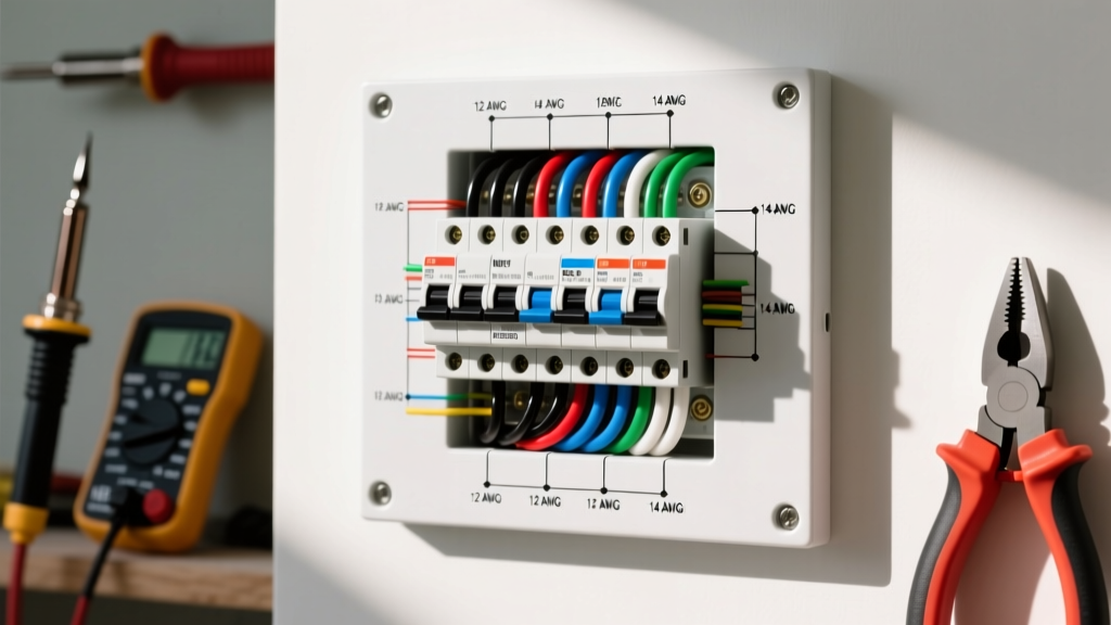
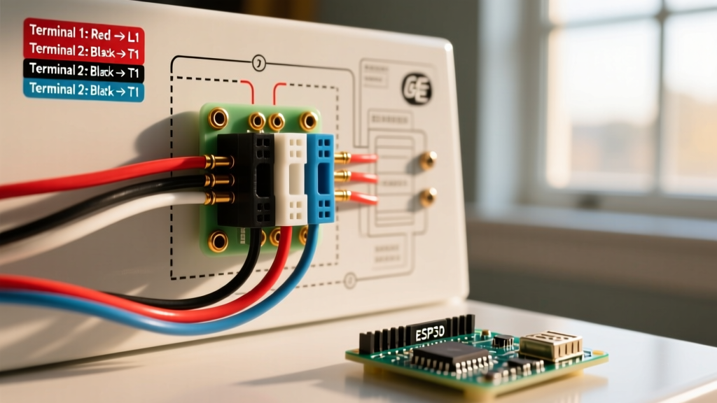
Before pulling wire through conduit, your diagram must accurately reflect the physical topology of a detached structure feed. A standard, code-compliant wiring diagram for a shed operating as a subpanel must include the following sequence:
- Main Service Panel: A dedicated 240V double-pole breaker (e.g., 50A, 60A, or 100A) serving as the disconnect and overcurrent protection.
- The Feeders: Four individual conductors (two hots, one neutral, one ground) routed through underground PVC conduit or direct-buried via UF-B cable.
- Shed Subpanel: A main-lug panel (such as the Siemens P2S1212L1100CU 100A panel, typically retailing around $95) featuring separated neutral and ground bus bars.
- Grounding Electrode System: Two 5/8-inch by 8-foot copper-clad ground rods driven at the shed, bonded to the subpanel ground bar.
Wire Gauge Selection and Voltage Drop Calculations
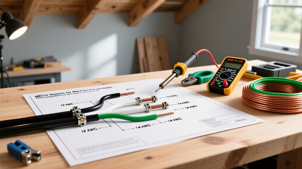
The most common failure point in shed wiring diagrams is sizing the wire strictly for ampacity while ignoring voltage drop. The NEC recommends a maximum 3% voltage drop on branch circuits and a combined 5% on feeders and branch circuits. When your shed is 100 feet away from the main house panel, standard ampacity charts are insufficient.
2026 Copper vs. Aluminum Feeder Sizing Chart
Due to the high cost of copper in 2026, many electricians are transitioning to XHHW-2 Aluminum wire for long shed runs. Below is a reference matrix for a 240V single-phase feed, keeping voltage drop under 3% at a full 80% continuous load.
| Distance (Main to Shed) | 50A Subpanel Feed | 60A Subpanel Feed | 100A Subpanel Feed |
|---|---|---|---|
| 50 Feet | #6 AWG Copper / #4 AL | #6 AWG Copper / #4 AL | #3 AWG Copper / #1 AL |
| 100 Feet | #4 AWG Copper / #2 AL | #3 AWG Copper / #1 AL | #1 AWG Copper / #2/0 AL |
| 150 Feet | #2 AWG Copper / #1/0 AL | #1 AWG Copper / #2/0 AL | #1/0 AWG Copper / #4/0 AL |
Expert Tip: If you are using THHN/THWN-2 copper wire in conduit, you must calculate the final ampacity based on the 75°C column of NEC Table 310.16, because standard residential breaker terminals are rated for 75°C per NEC 110.14(C), even if the wire insulation is rated for 90°C.
NEC Color Code Mandates for Shed Feeders
A wiring diagram for a shed is only as good as its physical execution. Inspectors will immediately red-tag a shed subpanel if the feeder wire color codes violate NEC 310.12. When pulling individual THHN/THWN-2 conductors through your 1.5-inch Schedule 80 PVC conduit, you must adhere to the following color matrix:
- Hot Leg 1 (Phase A): Black
- Hot Leg 2 (Phase B): Red (or Blue for 3-phase commercial applications)
- Neutral (Grounded Conductor): White or Gray. Never use black or red tape to mark a white wire as a hot in a feeder; the neutral must remain continuously white or gray.
- Equipment Grounding Conductor (EGC): Bare copper or Green (or Green with a Yellow stripe).
Note on UF-B Cable: If your diagram calls for direct-burial Underground Feeder (UF-B) cable instead of conduit, the jacket is typically gray, but the internal conductors are pre-colored Black, Red, White, and Bare. You must trench UF-B at a minimum depth of 24 inches, whereas PVC conduit with THHN only requires an 18-inch trench depth per NEC Table 300.5.
The Isolated Neutral Rule: Why Sheds Differ from Main Panels
The most critical distinction between your home's main service panel and your shed's subpanel is the treatment of the neutral and ground. In a main panel, the neutral bar and ground bar are bonded together. In a shed subpanel, they must be strictly isolated.
Step-by-Step Subpanel Isolation
- Remove the Bonding Screw: Panels like the Square D HOM816L100TC ship with a green bonding screw or strap connecting the neutral bar to the metal enclosure. You must physically remove this before wiring.
- Install an Add-On Ground Bar: Since the neutral bar is now floating (isolated from the metal box), you must install a separate ground bar (e.g., Square D HOMGB2) directly to the metal enclosure using the pre-tapped holes.
- Terminate Correctly: All white neutral wires from the shed's branch circuits go to the floating neutral bar. All bare/green ground wires, plus the feeder ground and the ground rod wire, go to the bonded ground bar.
Why this matters: If you bond the neutral and ground at the shed, return current will split and travel back to the main house via both the neutral wire and the ground wire (and potentially the earth). This creates parallel neutral currents, which can energize the metal enclosure of your shed tools, trip upstream GFCI breakers, and violate NEC 250.142.
Executing the Physical Pull and Torque Specifications
Modern NEC codes require documented torque specifications for all breaker and bus bar terminations. Relying on 'hand-tight' is no longer acceptable and will fail a 2026 inspection.
- Conduit Sizing: For a 100A shed feed using four #1 AWG THHN wires, a 1-inch conduit is mathematically allowed but practically impossible to pull. Upgrade to 1.5-inch Schedule 80 PVC to maintain an easy pull and accommodate future upgrades.
- Pulling Lubricant: Use a specialized wire pulling lubricant like PolyWater Yellow-77. Do not use dish soap, which dries out and degrades THHN insulation over time.
- Torque Tools: Use an insulated torque screwdriver, such as the Klein Tools 69010, set to the exact inch-pound rating printed on the breaker label (typically 45-50 in-lbs for 100A lugs). This satisfies NEC 110.14(D) requirements.
Common Shed Wiring Failure Modes to Avoid
Even with a perfect wiring diagram for your shed, field conditions introduce edge cases that cause system failures. Watch out for these specific pitfalls:
1. Sizing the Grounding Electrode Conductor (GEC) Incorrectly
While your main EGC running back to the house must match the size dictated by Table 250.122, the wire connecting your shed's ground bar to the exterior ground rods is governed by Table 250.66. For a 100A subpanel, the GEC to the ground rods only needs to be #8 AWG bare copper, though many electricians default to #6 AWG for physical durability against weed whackers and rodents.
2. Using NM-B (Romex) in Wet Conduit
A frequent DIY mistake is transitioning from underground PVC conduit into the shed wall and continuing to use indoor NM-B (Romex) cable. If the underground conduit inevitably collects condensation or groundwater, the paper-wrapped NM-B will wick moisture directly into your subpanel. Always transition to individual THWN-2 wires or use wet-location rated fittings.
3. Ignoring the Disconnecting Means
NEC 225.31 requires a disconnecting means for the shed. While a main breaker installed in the shed subpanel satisfies this requirement, if you use a main-lug panel without a main breaker, you must install a separate exterior disconnect switch within sight of the shed.
Further Reading and Code References
To ensure your specific municipal amendments are met, always cross-reference your local building department's guidelines. For deep-dive technical data, consult the following authoritative resources:
- NFPA 70: National Electrical Code (NEC) Standards Directory - The definitive source for all grounding, bonding, and wire sizing tables referenced in this guide.
- Southwire Voltage Drop Calculator - An essential tool for verifying your AWG selections against specific load distances and ambient temperature derations.
- OSHA Electrical Safety Standards - Critical guidelines for trenching safety, lockout/tagout procedures at the main panel, and PPE requirements when terminating live feeds.
By treating your wiring diagram for a shed as a strict engineering document rather than a loose sketch, you guarantee a system that is safe, efficient, and fully compliant with modern electrical codes.