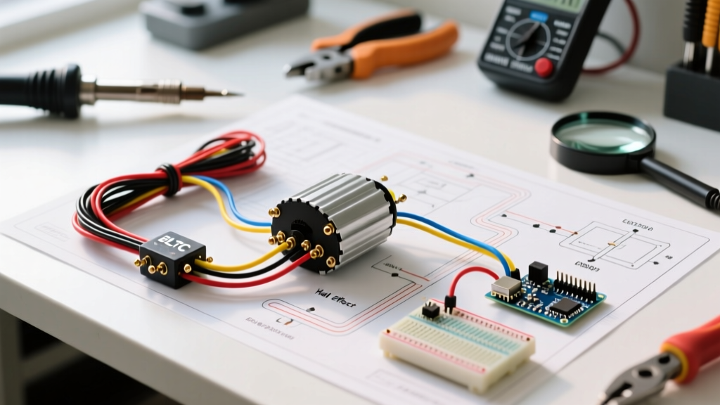

Decoding the Electric Scooter Wiring Schematic
When upgrading or repairing a high-performance electric scooter, the electric scooter wiring schematic is your most critical reference document. Modern high-power scooters, particularly those utilizing 48V to 72V Brushless DC (BLDC) hub motors like the QS Motor 205 or the 1500W VEVOR equivalents, rely on complex controller logic to manage phase commutation, regenerative braking, and thermal protection. Misinterpreting a single wire on the schematic can instantly destroy the controller's MOSFETs or cause a catastrophic lithium-ion battery venting event.
In this 2026 motor wiring tutorial, we will break down the anatomy of a standard BLDC electric scooter wiring schematic, detailing exact wire gauges, pinout logic, and the physical installation techniques required to handle high-amperage DC current safely.
CRITICAL SAFETY WARNING: DC systems operating above 48V can sustain lethal electrical arcs. Always disconnect the main battery loop and use a pre-charge resistor (typically a 100-ohm 50W power resistor) when initially connecting the battery to the controller capacitors to prevent spark-welding your XT90 or QS-S connectors.
Anatomy of the BLDC Controller Pinout
A typical 72V 40A controller schematic (such as those found in Sabvoton or generic square-wave/sine-wave units) divides wiring into three distinct categories: Power, Motor Commutation, and Low-Voltage Logic. Below is the standardized color-coding and gauge requirement for modern high-performance builds.
| Wire Group | Standard Color Code | Function | Required AWG (at 40A Cont.) |
|---|---|---|---|
| Main Power | Thick Red / Thick Black | Battery Positive (B+) and Ground (B-) | 8 AWG Silicone |
| Phase Wires | Thick Yellow, Green, Blue | Motor Stator Commutation (U, V, W) | 12 AWG to 10 AWG Silicone |
| Hall Sensors | Thin Red, Black, Yellow, Green, Blue | Rotor Position Feedback (5V Logic) | 22 AWG to 24 AWG (Shielded) |
| Throttle | Red (5V), Black (GND), White (Signal) | Speed Command Input (0.8V - 4.2V) | 22 AWG |
| Auto-Learn | Two White or Two Blue wires | Phase Angle & Hall Sequence Calibration | 22 AWG |
Step-by-Step Motor Wiring Tutorial
1. The Power Stage: Battery to Controller
The heaviest wires on your electric scooter wiring schematic are the main power leads. For a 72V 40A system, peak currents during hard acceleration can spike to 120A for several seconds. Using standard PVC-insulated 12 AWG wire will result in voltage sag and melted insulation. You must use 8 AWG high-strand-count silicone wire.
Terminate these wires using genuine Amass XT90-S anti-spark connectors. The 'S' variant includes a built-in pre-charge resistor in the male half, which safely charges the controller's massive electrolytic filter capacitors before the main contacts mate. According to Battery University, managing high-current discharge from parallel Li-ion cell groups requires minimizing connection resistance to prevent localized cell overheating.
2. Phase Wires: Controller to Hub Motor
The phase wires (Yellow, Green, Blue) carry the pulsed DC current that creates the rotating magnetic field in the stator. A common failure mode in DIY scooter builds is phase wire chafing inside the hollow motor axle.
Pro-Tip: Never use standard butt-splice crimps for phase wires. The vibration of the scooter will fatigue the copper strands. Instead, use closed-end copper crimp lugs, and apply a layer of adhesive-lined heat shrink tubing rated for 125°C. The resistance across any two phase wires should measure less than 0.1 ohms on a high-precision multimeter.
3. Hall Sensor Calibration and Logic
BLDC motors require precise rotor position data to commutate correctly. This is provided by three internal Hall effect sensors. The 5-pin JST connector on your schematic will carry:
- Red: +5V DC Power (Supplied by the controller's internal voltage regulator)
- Black: Ground
- Yellow/Green/Blue: Signal outputs for phases A, B, and C
Throttle and Brake Cutoff Logic
The throttle circuit on an electric scooter wiring schematic is a simple voltage divider. A standard hall-effect thumb throttle outputs a linear voltage between 0.8V (idle)4.2V (full throttle).
If your scooter exhibits 'ghost throttling' (the motor engages without user input), the 5V logic wire is likely picking up electromagnetic interference (EMI) from the thick phase wires. To resolve this, route the low-voltage logic harness on the opposite side of the scooter's steering stem from the high-current phase wires, or upgrade to a shielded signal cable with the shield grounded exclusively at the controller end.
Brake levers feature a simple normally-open (NO) or normally-closed (NC) microswitch. The schematic will designate a 'Low-Active' or 'High-Active' brake pin. Connecting a brake lever pulls the signal pin to ground (or 5V), instantly cutting the PWM signal to the MOSFETs and engaging regenerative braking if supported by the firmware.
Advanced Upgrades: Moving to VESC Architecture
While generic square-wave and basic sine-wave controllers are cheap (typically $45 to $85), serious builders in 2026 are migrating to VESC-based controllers (like the FlipSky 75100 or MakerX DV8). The VESC Project, originally developed by Benjamin Vedder, utilizes Field Oriented Control (FOC).
FOC completely changes the electric scooter wiring schematic by requiring highly precise motor parameter measurements (Flux Linkage, Inductance, and Resistance) via USB tuning software. FOC eliminates the audible 'hum' of square-wave controllers, increases range by up to 15%, and provides incredibly smooth regenerative braking. As detailed in technical analyses by All About Circuits, FOC algorithms continuously calculate the rotor angle using complex math rather than relying solely on the discrete 120-degree steps provided by physical Hall sensors, allowing for 'sensorless' operation at higher RPMs.
Troubleshooting Common Schematic Faults
When your build fails to power on or throws an error code on your QS-S4 display, use this diagnostic matrix based on standard controller fault logic:
- Error 07 (High Voltage Protection): Your battery's BMS is outputting a voltage higher than the controller's capacitor rating. If you are running a 20S Li-ion pack (84V fully charged), ensure your controller is rated for at least 90V. Never use a 72V nominal controller on a 20S pack.
- Error 08 (Hall Sensor Fault): Use a multimeter to back-probe the 5-pin JST connector while the system is on. You must read exactly 5.0V between the Red and Black wires. If you read 0V, the controller's internal 5V LDO regulator has burned out, usually due to a shorted hall sensor inside the motor hub caused by water ingress.
- Error 10 (Phase Wire Short): Disconnect the motor phase wires from the controller. Set your multimeter to continuity mode. Test between the controller's Yellow phase output and the Red battery positive wire. If you hear a beep, a MOSFET has shorted closed, and the controller must be replaced or rebuilt.
Final Assembly and Thermal Management
Once your electric scooter wiring schematic has been fully executed and verified, thermal management becomes your primary concern. High-amperage controllers generate significant heat. Mount the controller to the scooter's aluminum deck using thermal pads (minimum 3.0 W/mK thermal conductivity) rather than direct thermal paste, as the deck acts as a massive passive heatsink. Ensure all wire loops have at least 2 inches of slack before entering the controller housing to prevent the waterproofing grommets from pulling loose during suspension compression.