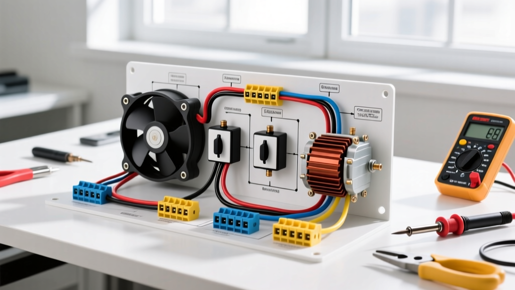

Introduction to PSC Fan Motor Wiring in Appliances
When servicing HVAC air handlers, commercial range hoods, or heavy-duty window air conditioners, understanding the wiring diagram for fan motor configurations is non-negotiable. The Permanent Split Capacitor (PSC) motor remains the workhorse of the appliance industry due to its high starting torque, reliability, and cost-effectiveness. While the industry is gradually shifting toward Electronically Commutated Motors (ECMs) for premium 2026 appliance models, PSC motors still account for over 65% of replacement parts in the residential and light commercial sector.
This comprehensive appliance wiring tutorial focuses on the ubiquitous 3-speed PSC fan motor (such as the widely used Fasco D7909 or Dayton 1TDR7 1/4 HP models). We will decode the schematic, detail the exact terminal connections, and provide actionable multimeter troubleshooting data to help you diagnose open windings or failing run capacitors safely.
Safety Directive: Before touching any terminal, execute a strict Lockout/Tagout (LOTO) procedure. Verify zero voltage at the contactor and motor terminals using a CAT III or CAT IV multimeter (e.g., Fluke 117). Per NFPA 70 (National Electrical Code) Article 430, motor circuits must be properly disconnected and grounded during maintenance to prevent lethal arc flash or shock hazards.
Decoding the Standard 3-Speed PSC Wire Color Code
Unlike single-speed motors, a 3-speed PSC motor utilizes tapped windings to alter the magnetic field strength, thereby controlling the rotor speed. While manufacturers occasionally deviate, the industry-standard wire color code for 208-230V appliance fan motors follows a strict hierarchy. Always cross-reference this with the specific schematic glued to the motor's belly band, but use this matrix as your baseline diagnostic tool.
| Wire Color | Terminal / Function | Speed / Circuit Note |
|---|---|---|
| White | Common (Line 2 / Neutral) | Completes the circuit for all speed taps. Connected directly to the L2 power leg or neutral bus. |
| Black | High Speed | Lowest winding resistance. Bypasses auxiliary taps for maximum RPM (e.g., 1075 RPM). |
| Blue | Medium Speed | Medium winding resistance. Engages partial auxiliary winding (e.g., 825 RPM). |
| Red | Low Speed | Highest winding resistance. Engages full auxiliary winding for minimum RPM (e.g., 600 RPM). |
| Brown | Capacitor Lead 1 | Connects exclusively to one terminal of the run capacitor. Never connect to line voltage. |
| Brown w/ White Tracer | Capacitor Lead 2 | Connects to the opposite run capacitor terminal and splices internally to the Common winding. |
Step-by-Step Wiring Tutorial: 1/4 HP PSC Motor Integration
Let us walk through the physical wiring sequence for a standard 1/4 HP, 208-230V, 3-speed PSC motor replacing an OEM air handler blower. This procedure assumes you are wiring for 'High' speed continuous operation, which is standard for cooling cycles.
Phase 1: Capacitor Sizing and Connection
The run capacitor is the heart of the PSC motor's phase-shift mechanism. Using the wrong microfarad (MFD) rating will result in excessive amperage draw, overheating, and premature winding failure.
- Identify the Rating: Check the motor nameplate. A typical 1/4 HP motor requires a 5 MFD, 370VAC run capacitor. (Note: Always match the MFD exactly, but you can safely upgrade the voltage rating to 440VAC for better surge tolerance in areas with dirty power grids).
- Connect the Browns: Attach the solid Brown wire to one capacitor terminal (C). Attach the Brown with White Tracer wire to the other capacitor terminal (FAN or HERM, depending on if it is a dual-run capacitor).
- Secure the Spade Connectors: Use a crimping tool to ensure tight 1/4-inch female spade connections. Loose capacitor terminals cause micro-arcing, which destroys the capacitor's internal dielectric film within weeks.
Phase 2: Line Voltage and Speed Selection
With the capacitor circuit isolated, we now route the line voltage through the appliance's control board or relay.
- Route the Common: Connect the White wire directly to the L2 (240V) or Neutral (120V) terminal on the main control board or contactor. This wire must remain unswitched.
- Select the Speed Tap: For maximum cooling airflow, select the Black (High) wire. Connect this to the 'Fan' or 'G' terminal on your thermostat relay or the 'EAC/FAN' terminal on the control board.
- Isolate Unused Taps: This is a critical safety step. The unused Blue (Medium) and Red (Low) wires will generate back-EMF (electromotive force) when the motor spins. If left bare, they can short against the chassis. Cap each unused wire individually with a closed-end crimp connector or heat shrink tubing. Do not just tape them, as adhesive tape degrades in the 120°F+ environment of an appliance blower compartment.
Multimeter Troubleshooting: Winding Resistance Verification
When an appliance fan fails to start, hums loudly, or trips the breaker, you must verify the integrity of the internal copper windings. According to expert electrical diagnostic guidelines, ohmmeter testing is the fastest way to isolate a bad motor from a bad capacitor or control board.
Set your multimeter to the lowest Ohms (Ω) setting. Zero the leads, then test between the White (Common) wire and each speed tap. Record your findings against the matrix below.
| Test Points | Expected Resistance (Ω) | Diagnostic Interpretation |
|---|---|---|
| White to Black (High) | 3.0Ω - 6.0Ω | Lowest resistance. Reads main winding only. If 'OL' (Open Line), the main winding is burnt open. |
| White to Blue (Med) | 7.0Ω - 12.0Ω | Medium resistance. Reads main + partial auxiliary. If significantly higher than spec, expect a high-resistance joint failure. |
| White to Red (Low) | 12.0Ω - 20.0Ω | Highest resistance. Reads main + full auxiliary winding. If reads 0.0Ω, windings are shorted internally. |
| White to Chassis (Ground) | OL (Infinite) | Must be infinite. Any reading below 2 Megaohms indicates winding insulation breakdown and a severe shock hazard. |
Edge Case: The 'Humming but Not Spinning' Failure Mode
If your resistance readings are perfectly normal, but the motor hums and refuses to rotate, the issue is almost certainly the run capacitor or a seized bearing. Before replacing the motor, perform a 'push test' with a non-conductive fiberglass stick. If the motor spins up to speed when pushed, the bearings are fine, and the capacitor has lost its MFD rating (dielectric degradation). Replace the capacitor with an identical MFD unit. Current market pricing for a premium 5 MFD / 440VAC capacitor (like the Genteq 97F series) is roughly $12 to $18 in 2026.
PSC vs. ECM: The 2026 Appliance Motor Landscape
While mastering the wiring diagram for fan motor setups based on PSC technology is essential for legacy repairs, technicians must recognize the regulatory shifts. The U.S. Department of Energy's Advanced Manufacturing Office continues to push for higher efficiency standards in residential appliances. Consequently, many 2026 high-end HVAC systems and commercial kitchen appliances now utilize ECM (Electronically Commutated Motors).
- Wiring Complexity: PSC motors use simple line-voltage taps. ECM motors use low-voltage communication cables (often 4-pin or 16-pin Molex connectors) to receive speed commands from an integrated control module.
- Cost Factor: A replacement PSC motor (e.g., Fasco D7909) costs between $85 and $140. An equivalent ECM motor and control module can cost $450 to $800, making accurate PSC troubleshooting a massive value-add for budget-conscious consumers.
- Efficiency: ECMs operate at 70-80% efficiency across all speeds, whereas PSC motors drop to 40-50% efficiency on their 'Low' speed taps due to the intentional resistance introduced by the auxiliary windings.
Final Inspection and Power-Up Protocol
Once all wires are terminated, capacitors secured, and unused taps insulated, perform a final visual inspection. Ensure no bare copper is exposed outside the wire nuts or spade connectors. Reinstall the blower housing, restore power at the disconnect, and engage the thermostat fan circuit. Use a clamp meter around the Black (High) speed wire to verify the running amperage. It should read 10% to 15% below the Full Load Amps (FLA) stamped on the motor nameplate (typically around 1.2A to 1.5A for a 1/4 HP unit). If the amperage is within spec and the airflow is turbulent-free, your wiring is complete and code-compliant.