
The Critical Role of Schematics in Low-Voltage Diagnostics
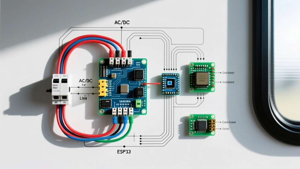
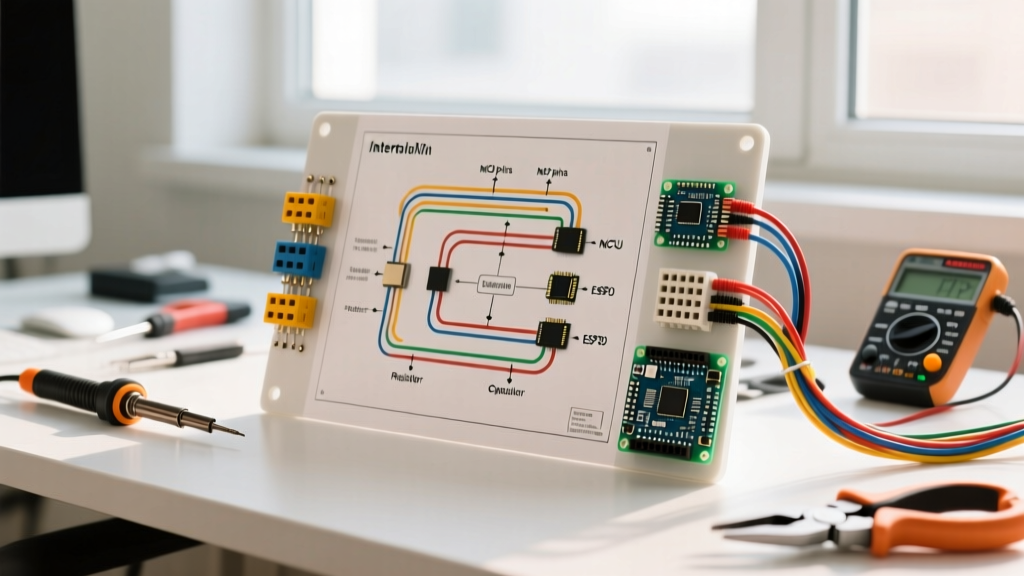
When a multi-tenant apartment intercom or a commercial office entry system fails, guessing which wire is faulty is a fast track to wasted labor and damaged components. As of 2026, while IP-based PoE systems are gaining market share, legacy analog and hybrid 4-wire bus systems still govern roughly 60% of existing multi-family residential builds. To effectively diagnose these systems, a technician must know how to interpret a wiring diagram for intercom architectures. The schematic is not just an installation map; it is a diagnostic flowchart that reveals voltage nodes, signal paths, and impedance requirements.
Troubleshooting without a diagram is like navigating a maze blindfolded. By cross-referencing physical symptoms with schematic nodes, you can isolate whether a failure stems from a degraded power supply, a shorted audio transformer, or an impedance mismatch in the video coax.
Decoding the Standard 4-Wire Intercom Topology
Most traditional hardwired systems, including legacy NuTone models and standard commercial setups, utilize a 4-wire plus shield topology. Understanding how these wires are represented on the schematic is the first step in fault isolation.
- Wire 1 (Power / VCC): Typically carries 12VDC to 24VDC from the central power supply to the substation. On the diagram, this traces back to the transformer and rectifier bridge.
- Wire 2 (Audio TX / Mic): Carries the outgoing audio signal from the substation microphone to the master station amplifier.
- Wire 3 (Audio RX / Speaker): Carries the amplified audio from the master station back to the substation speaker.
- Wire 4 (Common / Ground): The DC return path and signal reference ground.
- Shield / Video: In audio-only systems, the shield prevents RF interference. In video intercoms, a separate coaxial line or twisted-pair with a balun carries the 1Vp-p composite video signal.
Tracing the Audio Path: Superimposed Signals
A common point of confusion for junior technicians is measuring audio lines. In many 4-wire systems, the audio signal is not a standalone AC wave; it is an AC signal superimposed on a DC bias voltage. If your wiring diagram for intercom audio paths shows a capacitor in series with the speaker line, that capacitor is blocking DC while allowing AC audio frequencies to pass. When testing with a multimeter, you must switch from DC voltage mode to AC millivolt mode to accurately measure the audio ripple (typically 0.5V to 2V AC) while a user is speaking into the microphone.
Essential Diagnostic Toolkit for 2026
Accurate troubleshooting requires precision tools. Relying on a cheap hardware store multimeter will yield ghost voltages due to low input impedance. Here is the professional standard kit:
- True RMS Multimeter (e.g., Fluke 117): Priced around $220 in 2026, its low-impedance (LoZ) mode is critical for eliminating phantom voltages on long, unshielded intercom runs.
- Tone Generator and Probe (e.g., Klein Tools VDV526-200): Essential for tracing Wire 2 and Wire 3 through bundled conduit where wire labels have degraded.
- Oscilloscope or Video Line Monitor: Necessary for verifying the 1V peak-to-peak (1Vp-p) composite video signal and checking for synchronization pulse distortion.
- Decade Resistance Box: Used to simulate line resistance when testing master station amplifiers on the bench.
Intercom Fault Diagnostic Matrix
The following matrix maps common field symptoms to specific nodes on a standard wiring diagram, providing exact testing parameters and corrective actions.
| Symptom | Schematic Node | Expected Measurement | Failure Mode | Corrective Action |
|---|---|---|---|---|
| No Power at Substation | Wire 1 (VCC) to Wire 4 (GND) | 14.5VDC (at PSU) / >12VDC (at sub) | Voltage drop due to undersized wire or corroded terminal | Upgrade 22 AWG to 18 AWG; clean terminals with contact cleaner |
| Severe 60Hz Audio Hum | Wire 4 (Shield/Ground) | < 50mV AC between Master GND and Sub GND | Ground loop or broken shield braid | Verify single-point grounding at the master station PSU; replace shielded cable |
| Audio Cuts Out When Video is Active | PSU Current Limit Node | PSU output drops below 11VDC under load | Failing PSU filter capacitors cannot handle combined A/V current draw | Replace PSU filter caps or upgrade to a higher amperage linear power supply |
| Video Ghosting / Smearing | Video Coax / Balun Node | 1Vp-p at 75 ohms impedance | Impedance mismatch (using 110-ohm Cat5e without balun) | Install passive 75-to-110 ohm video baluns at both master and substation ends |
Real-World Case Study: Aiphone GT Series Voltage Drop
Consider a troubleshooting scenario involving an Aiphone GT series multi-tenant system. The master station (GT-1M) functions perfectly, but the furthest substation (GT-2C) intermittently drops offline, specifically when the electric door strike is triggered.
By consulting the wiring diagram for intercom power distribution, we note that the door strike and the substation share a common power bus. The run to the furthest apartment is 450 feet using 18 AWG copper wire.
The Math Behind the Failure
18 AWG copper has a resistance of approximately 6.385 ohms per 1,000 feet. A 450-foot run means a 900-foot round trip (positive and negative conductors), resulting in a total wire resistance of 5.74 ohms. When the door strike (drawing roughly 500mA) activates, the current on the bus spikes. Using Ohm's Law (V = I x R), the voltage drop across the wire is 0.5A x 5.74Ω = 2.87V. If the central power supply is outputting 14VDC, the substation only receives 11.13VDC during the strike activation. Because the GT-2C requires a minimum of 11.5VDC to maintain its microcontroller logic, it resets. The Fix: The schematic dictates a star topology for power distribution. The solution is to run a dedicated 16 AWG power line directly from the PSU to the distant substation, bypassing the door strike's voltage sag, or to install a local secondary power supply near the distant apartment.
'In low-voltage troubleshooting, the wiring diagram is your ultimate source of truth. Physical wire colors fade, get painted over, or are misused by previous installers. Always trust the schematic node designations over the physical jacket colors of the wires in the wall.'
Star vs. Daisy Chain: Topological Errors
A frequent cause of systemic failure is ignoring the topology specified in the wiring diagram. Many 4-wire audio systems require a Star Topology, where every substation's cable runs directly back to the master station or central distribution hub. If an installer uses a Daisy Chain (running wire from Sub 1 to Sub 2, then to Sub 3), two major issues occur:
- Signal Reflection: Audio and data signals hit the end of the line and reflect back, causing phase cancellation and echoing.
- Cumulative Voltage Drop: The first substation in the chain bears the current load for all subsequent substations, leading to severe voltage sag at the end of the line.
When troubleshooting an echoing audio fault, trace the physical wire path against the schematic. If the diagram shows a star but the physical wire is daisy-chained, you must pull new homerun cables.
Code Compliance and Safety Standards
While intercom wiring is considered low-voltage, it is strictly governed by electrical codes to prevent fire hazards and interference with life-safety systems. According to NFPA 70 (National Electrical Code) Article 725, intercom wiring typically falls under Class 2 or Class 3 remote-control and signaling circuits. Key code requirements to verify during troubleshooting and repair include:
- Separation from Line Voltage: Class 2 intercom cables must maintain a minimum 2-inch separation from 120V/240V AC power lines unless separated by a continuous, firmly fixed nonconductive barrier.
- Plenum Rating: If the intercom wiring is routed through an environmental air handling space (like a drop ceiling used for return air), the cable must be CMP (Communications Multipurpose Cable, Plenum) rated to prevent toxic smoke propagation during a fire.
- Grounding of Shields: The metallic shield of the intercom cable must be grounded to prevent it from acting as an antenna for EMI (Electromagnetic Interference), but it must be grounded at one end only to prevent ground loops.
Advanced Diagnostics: Using the Schematic to Inject Signals
For master station amplifier failures, the wiring diagram allows you to bypass the field wiring entirely. By locating the 'Audio In' node on the schematic (usually post-capacitor on the main PCB), you can use a portable audio tone generator to inject a 1kHz sine wave directly into the amplifier stage. If the master station speaker outputs a clean 1kHz tone, the amplifier is healthy, and the fault lies in the field wiring or the substation microphone. If the tone is distorted or absent, the master station's internal op-amps or output transistors have failed. This technique, championed by Fluke Networks' low-voltage diagnostic methodologies, saves hours of unnecessary cable pulling.
Conclusion
Mastering the wiring diagram for intercom troubleshooting transforms a chaotic, frustrating repair job into a systematic, logical process. By understanding the 4-wire topology, calculating voltage drops, respecting impedance requirements for video, and adhering to NEC Article 725, you ensure that the systems you repair are not only functional but safe and reliable for years to come. Always keep a digital copy of the manufacturer's schematic on your tablet, and let the diagram guide your multimeter probes.