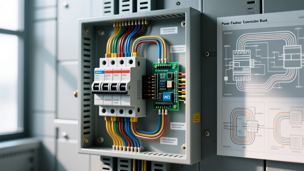

Defining the Blueprint: What Is an Electrical Wiring Diagram?
When apprentices and DIYers first ask what is electrical wiring diagram documentation, they often confuse it with a schematic. A wiring diagram is a simplified, conventional pictorial representation of an electrical circuit that shows the physical connections and physical layout of the components. Unlike a schematic diagram, which focuses on the logical flow and function of the circuit regardless of physical placement, a wiring diagram maps exactly how wires are routed, where they connect to terminals, and how they physically interact within an enclosure or building.
For residential and commercial electricians, the wiring diagram is the ultimate field guide. It dictates wire gauge, routing paths, breaker sizing, and terminal landing points. According to the Penn State Extension Residential Wiring Guide, misinterpreting these physical layouts is a leading cause of circuit overloads and improper bonding in DIY projects.
Diagram Taxonomy: Wiring vs. Schematic vs. Ladder
To execute a panel build correctly, you must understand which diagram you are looking at. Below is a comparison matrix of the three primary electrical diagrams used in the trade.
| Diagram Type | Primary Focus | Visual Style | Best Use Case |
|---|---|---|---|
| Wiring Diagram | Physical layout and routing | Pictorial, shows enclosures and terminal blocks | Panel wiring, appliance repair, physical installation |
| Schematic | Logical circuit function | Abstract symbols, straight lines, ignores physical space | Troubleshooting logic boards, PCB design, control logic |
| Ladder Diagram | Industrial control sequences | Rungs and rails resembling a ladder | PLC programming, motor control circuits, HVAC sequencing |
Step-by-Step Walkthrough: Executing a 200A Main Panel Diagram
To truly understand how to read and apply these diagrams, we will walk through the physical execution of a standard 200-Amp residential main service panel wiring diagram. This walkthrough assumes a standard split-phase 120/240V system using a Square D Homeline 42-space load center.
Step 1: Tracing the Service Entrance Conductors
The top section of any main panel wiring diagram begins at the utility drop or lateral. For a 200A service, the diagram will specify 4/0 AWG XHHW-2 Aluminum or 2/0 AWG THHN Copper for the two hot legs (L1 and L2), and the same gauge for the neutral (N).
- Action: Strip exactly 3/4 inch of insulation from the 4/0 aluminum conductors using a specialized cable knife to avoid nicking the strands.
- Action: Land L1 and L2 on the main breaker lugs. The diagram will show the neutral landing on the main neutral bar.
- Critical Code Check: Per NFPA 70 (NEC) Section 110.14(D), all terminations must be torqued to the manufacturer's specifications. For a Square D 200A main lug, this typically requires a calibrated torque wrench set to 250-300 inch-pounds. Hand-tightening leads to thermal expansion failures and arc faults.
Step 2: The Neutral-to-Ground Bond
A crucial element of the main panel wiring diagram is the bonding jumper. In a main service disconnect, the neutral bar and the ground bar must be bonded. In a subpanel, they must remain isolated.
NEC 250.24(A)(5): "A main bonding jumper shall be used to connect the equipment grounding conductor(s) and the service-disconnect enclosure to the grounded conductor within the enclosure for each service disconnect."
Execution: Locate the green bonding screw or bonding strap indicated on the diagram. Drive the bonding screw through the neutral bar into the threaded hole in the panel backbox. Torque to 45 inch-pounds. This ensures that in the event of a ground fault, current has a low-impedance path back to the source, tripping the breaker instantly.
Step 3: Routing 240V Double-Pole Branch Circuits
Moving down the diagram, you will encounter the 240V heavy appliance circuits. These require double-pole breakers that span both L1 and L2 bus bars to draw 240V.
- Electric Range (50A): The diagram calls for a 50A double-pole breaker (e.g., Square D HOM250) and 6 AWG copper NM-B or THHN wire. The wiring diagram will show a 4-wire configuration (Hot 1, Hot 2, Neutral, Ground) mandated for all modern ranges to separate the 120V control logic from the 240V heating elements.
- Electric Dryer (30A): Requires a 30A breaker (HOM230) and 10 AWG copper. Again, a 4-wire setup (NEMA 14-30R receptacle) is required by code.
- HVAC Condenser (30A-40A): Unlike indoor appliances, the outdoor HVAC disconnect wiring diagram will only require the two hot legs and a ground (no neutral), utilizing 8 AWG or 10 AWG THHN in liquid-tight flexible metal conduit.
Step 4: 120V Single-Pole Circuits and AFCI/GFCI Mandates
The bulk of the wiring diagram consists of 120V, 15A, and 20A single-pole branch circuits. Modern diagrams must reflect the latest NEC mandates for arc-fault (AFCI) and ground-fault (GFCI) protection.
Bedrooms and Living Areas: The diagram will specify Combination-Type AFCI breakers (e.g., HOM120CAFIC). These breakers feature a coiled white neutral pigtail that must land directly on the neutral bar, while the circuit's neutral wire lands on the breaker's neutral terminal. This allows the breaker's internal microprocessor to monitor the neutral for arc signatures.
Kitchens and Bathrooms: The diagram will route 20A circuits using 12 AWG copper to GFCI breakers or specify standard breakers paired with GFCI receptacles at the first point of the daisy chain. Pro-Tip: When wiring Multi-Wire Branch Circuits (MWBC) to share a neutral between two 120V circuits, the wiring diagram will explicitly show a handle-tie connecting the two single-pole breakers to ensure simultaneous disconnect, a strict NEC 210.4(B) requirement.
Essential Tools for Diagram Execution
Translating a wiring diagram into a safe, code-compliant physical installation requires specialized tools. Do not rely on standard hardware store gear for panel terminations.
- Calibrated Torque Screwdriver: The CDI 401SM (approx. $160) or Klein Tools QPE150. Essential for meeting NEC 110.14(D) lug torque requirements.
- Clamp Meter with Inrush: Fluke 375 or Klein CL800 ($110). Used to verify the ampacity drawn on the circuits mapped in the diagram post-installation.
- Wire Strippers for Solid/Stranded: Knipex Automatic Wire Strippers (approx. $45) to ensure clean removal of THHN insulation without scoring the copper, which creates hot spots.
- Circuit Tracer: Klein Tools ET910. Used to verify that the physical breaker matches the circuit directory mapped on the wiring diagram.
Common Wiring Diagram Edge Cases and Failures
Even with a perfect diagram, field conditions introduce edge cases. One common failure mode is neutral bar overcrowding. A standard 42-space panel may only have 42 neutral termination points. If the diagram includes AFCI breakers, GFCI receptacles, and MWBCs, you will quickly run out of neutral bar space. The solution, often noted in the addendum of professional wiring diagrams, is to install an accessory ground/neutral bar (e.g., Square D HOM816L125PGC) to expand termination capacity.
Another edge case involves wire bending space. NEC 312.6 dictates minimum bending space for conductors entering a cabinet. If your diagram calls for multiple 4/0 or 2 AWG wires entering a single knockout, you must use a pull box or a larger gutter enclosure to prevent insulation damage and inductive heating caused by cramming wires too tightly.
Summary
Understanding what an electrical wiring diagram is goes far beyond recognizing symbols; it is about understanding the physical, mechanical, and code-compliant execution of electrical power distribution. By tracing the diagram from the service entrance down to the smallest 15A AFCI branch circuit, and by utilizing calibrated tools to meet exact torque specifications, you ensure a system that is not only functional but fundamentally safe for decades of use.