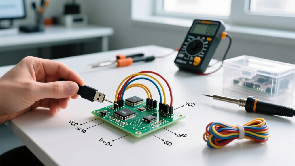

Decoding the Wiring Diagram for USB Standards
When engineering custom embedded systems, automotive infotainment harnesses, or permanent kiosk installations, relying on off-the-shelf cables is rarely an option. You must design the harness from scratch to meet specific spatial and electrical constraints. Understanding the core wiring diagram for USB protocols is the first step in preventing data corruption, negotiation failures, and power delivery bottlenecks. In 2026, with the widespread adoption of USB Power Delivery (PD) 3.1 Extended Power Range (EPR) pushing up to 240W, the margin for error in custom wire planning is virtually zero.
This installation planning guide breaks down the exact pinouts, wire gauge mathematics, shielding requirements, and termination workflows needed to execute a flawless custom USB harness.
Core Pinout Matrices: USB 2.0, 3.0, and Type-C
The fundamental wiring diagram for USB 2.0 relies on a simple 4-wire architecture, but as we move into SuperSpeed (USB 3.x) and Type-C, the complexity scales exponentially. Below is the baseline pinout matrix for standard Type-A and Type-B connections, which remain heavily used in industrial and legacy embedded systems.
USB 2.0 & 3.0 Type-A Pinout Reference
| Pin | Standard Color | Function | Signal Type & Tolerance |
|---|---|---|---|
| 1 | Red | VBUS (+5V) | Power (±5% / 4.75V - 5.25V) |
| 2 | White | D- | High-Speed Data (90Ω differential) |
| 3 | Green | D+ | High-Speed Data (90Ω differential) |
| 4 | Black | GND | Power Return / Signal Ground |
| 5* | Blue | StdA_SSRX- | SuperSpeed Receive (USB 3.x only) |
| 6* | Yellow | StdA_SSRX+ | SuperSpeed Receive (USB 3.x only) |
| 7* | Black | GND_DRAIN | SuperSpeed Ground Return |
| 8* | Purple | StdA_SSTX- | SuperSpeed Transmit (USB 3.x only) |
| 9* | Orange | StdA_SSTX+ | SuperSpeed Transmit (USB 3.x only) |
* Pins 5-9 apply exclusively to USB 3.0/3.1/3.2 Type-A SuperSpeed architectures.
The USB Type-C & PD 3.1 Paradigm Shift
The wiring diagram for USB Type-C abandons the legacy pinout in favor of a 24-pin reversible architecture. For custom installations planning to support USB PD 3.1 (up to 48V at 5A for 240W), your harness must include dedicated CC1 and CC2 (Configuration Channel) lines. These pins negotiate the power role and voltage. If you omit the CC lines or wire them with incorrect pull-up/pull-down resistors (typically 5.1kΩ pull-down on the sink), the source will default to 5V/900mA, crippling your high-power installation.
Wire Gauge Selection & Voltage Drop Calculations
A common failure mode in custom kiosk and automotive builds is selecting wire gauges based solely on ampacity tables, ignoring voltage drop. The USB specification mandates that VBUS must not drop below 4.75V at the device connector under maximum load. If your power supply outputs 5.1V at the panel, you only have a 0.35V budget for the entire cable run (both the VBUS and GND return paths).
AWG Decision Matrix for 5V USB 2.0 Power Lines
Assuming a standard 500mA (USB 2.0) or 1.5A (USB BC 1.2) draw, here is the maximum one-way cable length before violating the 4.75V threshold, based on copper wire resistance at 20°C.
| Wire Gauge (AWG) | Resistance (Ω per 10 ft) | Max Length @ 500mA (0.25V drop limit) | Max Length @ 1.5A (0.25V drop limit) | Recommended Use Case |
|---|---|---|---|---|
| 28 AWG | 0.653 Ω | 1.9 meters (6.2 ft) | 0.6 meters (2.0 ft) | Internal PCB jumpers, ultra-short pigtails |
| 24 AWG | 0.257 Ω | 4.8 meters (15.7 ft) | 1.6 meters (5.2 ft) | Standard commercial cables, short panel runs |
| 22 AWG | 0.162 Ω | 7.7 meters (25.2 ft) | 2.5 meters (8.2 ft) | Automotive dash-to-console routing |
| 20 AWG | 0.102 Ω | 12.2 meters (40.0 ft) | 4.0 meters (13.1 ft) | Permanent kiosk installations, long conduit runs |
Pro-Tip for High-Power PD Installations: If you are routing 20V/5A (100W) or 48V/5A (240W) over custom distances, the voltage drop percentage becomes more forgiving at higher voltages, but thermal management becomes critical. Always use a minimum of 18 AWG for the VBUS and GND lines in any harness expected to sustain 5A continuous current, and verify thermal rise using an infrared camera during the 48-hour burn-in test.
Shielding and Grounding Strategies for EMI Mitigation
High-speed USB data lines (D+/D- at 480 Mbps, and TX/RX pairs at 10 Gbps+) are highly susceptible to Electromagnetic Interference (EMI). When planning your installation, you must specify the correct shielding topology. According to the USB Implementers Forum (USB-IF), unshielded cables are only viable for lengths under 50cm in low-noise environments.
- Foil Shielding (Aluminum/Polyester): Provides 100% coverage against high-frequency RFI. Essential for routing near switching power supplies or variable frequency drives (VFDs). Must include a continuous drain wire (typically 24 AWG tinned copper) for termination.
- Braided Shielding (Tinned Copper): Offers superior low-frequency noise rejection and mechanical strength. Ideal for cables subjected to continuous flexing (e.g., cable carriers in CNC machines). Coverage is typically 85-95%.
- Combination (Foil + Braid): Mandatory for USB 3.x and USB4 installations routed through industrial control panels. Expect to pay a premium (roughly $4.50 to $6.00 per foot for Alpha Wire 6360 series multi-conductor shielded cables in 2026), but it guarantees signal integrity.
The Ground Loop Trap
A frequent edge case in custom metal-enclosure installations is the creation of a ground loop via the USB shield. The shield should be tied to the chassis ground at the host end only. At the device end, the shield and drain wire must be left floating (or terminated via a high-value resistor and capacitor network) to prevent low-frequency ground currents from modulating the data lines.
Step-by-Step Installation Planning Workflow
Follow this systematic workflow to transition from schematic to physical harness:
- Load Profiling: Determine the maximum concurrent power draw and data bandwidth. A diagnostic OBD-II dongle requires vastly different wire planning than a 100W USB-C PD charging port.
- Impedance Matching: Specify twisted-pair cabling for D+/D- with a strict 90Ω ±15% differential impedance. Use a Time Domain Reflectometer (TDR) on your first prototype batch to verify the cable manufacturer's specs.
- Bend Radius Calculation: Never route high-speed USB cables at sharp 90-degree angles. Maintain a minimum bend radius of 4x the cable's outer diameter to prevent altering the dielectric constant and ruining the impedance profile.
- Termination Selection: Avoid hand-soldering directly to PCB pads for field-replaceable harnesses. Use high-reliability connectors like the Molex 214755 series (USB-C) or JST-SH 1.0mm pitch connectors for internal board headers. Budget approximately $1.85 to $3.20 per mating pair for genuine Molex components.
- Continuity & Resistance Testing: Before applying power, use a high-precision multimeter (such as the Fluke 87V) to measure the end-to-end resistance of the VBUS and GND lines. Refer to standard multimeter resistance testing protocols to ensure your readings account for test-lead resistance. Any VBUS loop reading above 0.3Ω warrants a thicker gauge.
Common Failure Modes & Troubleshooting Edge Cases
Even with a perfect wiring diagram for USB, physical installation realities can introduce faults. Here are the most common edge cases encountered in the field:
1. Intermittent Device Enumeration (The "Chirp" Failure)
Symptom: The host OS repeatedly plays the USB connect/disconnect sound; device never mounts.
Root Cause: The D+ and D- lines are not routed as a tightly coupled twisted pair, or the cable was zip-tied too tightly, crushing the dielectric and altering the 90Ω impedance. The host's high-speed "chirp" protocol fails to negotiate, dropping the connection back to Full-Speed (12 Mbps) or failing entirely.
Solution: Re-terminate using looser lacing ties or Velcro straps. Ensure the D+/D- pair is separated from the VBUS line by at least 2mm internally to prevent capacitive coupling.
2. USB-C PD Negotiation Stalling at 5V
Symptom: A custom 100W USB-C port only outputs 5V/3A, refusing to negotiate 20V.
Root Cause: The CC1/CC2 lines were wired with standard 28 AWG wire over a long distance, or the pull-down resistors on the sink side are out of tolerance. The PD negotiation packets are corrupted by voltage sag on the CC lines.
Solution: Verify the 5.1kΩ pull-down resistors on the Type-C receptacle using a precision ohmmeter. Ensure CC lines are shielded from the high-current VBUS lines.
3. Thermal Runaway in VBUS Crimps
Symptom: The connector housing melts or emits a burning plastic odor after 30 minutes of 3A+ charging.
Root Cause: Poor crimping technique on the VBUS wire. A loose crimp introduces a high-resistance point (e.g., 0.1Ω). At 3A, this single point dissipates 0.9W of heat (P = I²R), which is enough to melt standard nylon connector housings.
Solution: Use calibrated ratcheting crimpers specific to your terminal type (e.g., Molex Hand Crimp Tool 63811-1000). Perform a pull-test and a millivolt drop test across the crimp joint under load.
Compliance and Safety Standards
When installing custom USB wiring in commercial buildings, permanent kiosks, or marine environments, you must adhere to local electrical codes. In the United States, low-voltage data and power circuits are governed by NFPA 70 (National Electrical Code) Article 725. While USB power (under 60V DC) generally falls under Class 2 or Class 3 circuit classifications, routing USB cables in the same conduit as 120V/240V AC mains is strictly prohibited unless separated by a continuous metallic barrier. Always plan your conduit routing to maintain a minimum 2-inch separation from AC lines to prevent inductive coupling and ensure fire safety compliance.
Final Thoughts on Harness Engineering
Designing a custom USB harness is an exercise in managing high-frequency signal integrity alongside DC power delivery. By strictly adhering to the wiring diagram for USB standards, calculating voltage drop rather than guessing wire gauges, and implementing rigorous shielding and termination protocols, you can build installations that are both robust and fully compliant with modern 240W PD specifications. Always prototype a single harness and subject it to TDR and thermal testing before committing to a full production run.