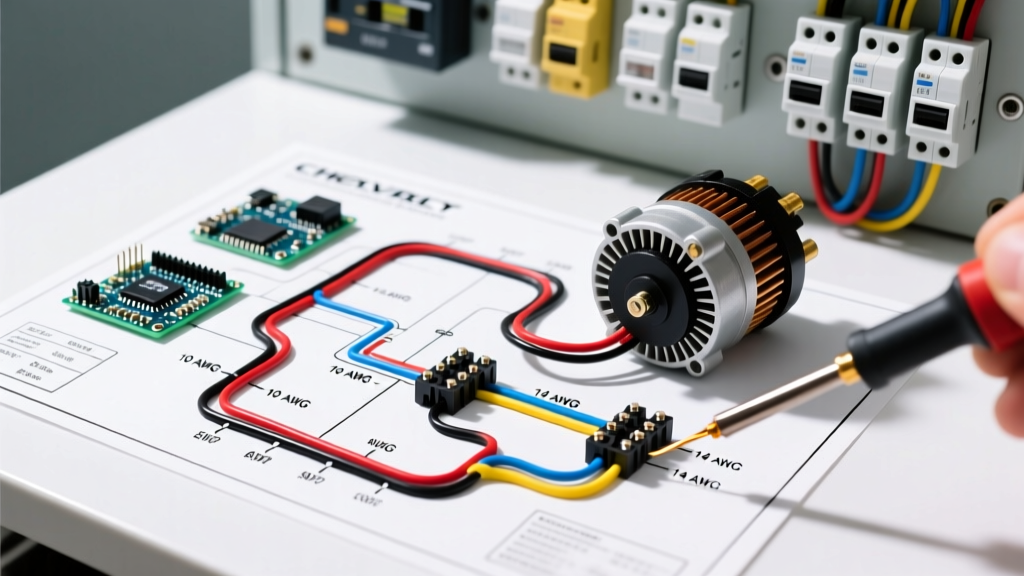

The Evolution of Chevy Charging Systems and Panel Protection
Upgrading a Chevrolet vehicle from a stock 63-amp Delco 10SI to a 145-amp AD244 or a modern 200+ amp high-output unit (such as a Mechman or Powermaster) requires far more than simply bolting a new unit to the engine bracket. The factory wiring harness, fuse panel, and dash-mounted ammeter shunts were engineered for the low-draw electrical systems of the 1970s through 1990s. Pushing 2,500+ watts of continuous DC current through aging factory copper is a primary cause of alternator fires and melted bulkhead connectors in classic C10 trucks, Camaros, and restomod builds.
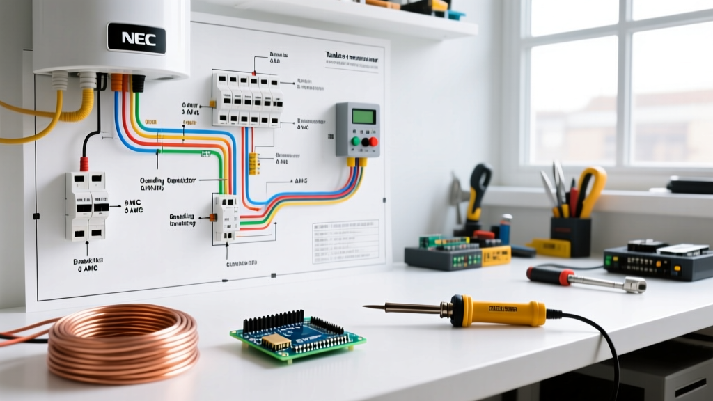
As of 2026, the standard for high-amperage automotive charging circuits dictates a complete bypass of the factory ammeter loop in favor of a dedicated, properly fused charge wire routed to a secondary distribution block. This guide breaks down the exact wiring diagram for alternator Chevy configurations, focusing on terminal pinouts, overcurrent protection device (OCPD) sizing, and heavy-gauge wire routing to ensure your electrical panel can handle the load safely.
Decoding the Wiring Diagram for Alternator Chevy Terminals
Whether you are working with a classic 12SI, a 1990s CS130/CS144, or a modern AD230/AD244, understanding the regulator plug is critical. The most common point of failure in Chevy alternator swaps is misinterpreting the remote sense and field terminals. According to the MAD Electrical Alternator Tech Guide, the Delco Remy voltage regulators rely on specific feedback loops to maintain a steady 14.2V to 14.4V output.
- B+ (BAT Terminal): The main output stud. Connects directly to the battery positive via the main charge wire and primary OCPD (fuse/breaker).
- S (Sense Terminal): Measures actual system voltage. Critical: This must be routed to the battery positive or main distribution busbar. If left unconnected or jumpered to the alternator case, the regulator will read voltage at the alternator, resulting in severe undercharging at the battery due to voltage drop across the wire run.
- L (Lamp/Ignition Terminal): Used to trigger the internal regulator and illuminate the dash 'GEN' or 'ALT' warning light. Requires a 10-ohm to 100-ohm resistor or a standard 194 incandescent bulb in parallel to prevent regulator burnout on older models.
- F (Field Terminal): Provides a 12V+ signal for tachometers or computer-controlled field modulation on newer LS/LT swap ECMs.
- P (Phase Terminal): Outputs an AC stator ripple signal, primarily used for diagnostic scopes or specific tachometer calibrations.
1-Wire vs. 3-Wire Regulator Configurations
While '1-wire' alternators are heavily marketed for their simplicity (requiring only the B+ charge wire), they are fundamentally flawed for high-draw panels. A 1-wire setup relies on internal sensing at the alternator case. In a vehicle with a high-draw audio system, electric water pump, or EFI setup, the voltage at the battery can drop to 12.8V while the alternator reads 14.4V locally, leaving your battery chronically undercharged. A true 3-wire diagram utilizing the Delco PT113 or PT1157 pigtail connector to route the 'S' terminal directly to the starter solenoid or main busbar is mandatory for any system exceeding 120 amps.
Breaker Sizing and Fuse Panel Bypass Strategy
The factory Chevy bulkhead connector and dash ammeter act as a massive bottleneck. Running a 150-amp AD244 through a 1978 C10 dash harness will melt the firewall plug within minutes of high-load operation. The correct approach is to bypass the dash entirely, pegging the factory ammeter needle to 'Charge' via a simple 12V ignition switch wire, and routing the heavy current directly to the battery.
Expert Panel Rule: Never use a standard automotive circuit breaker (like the 50-amp metal-clad GM breakers) for alternator outputs exceeding 100 amps. The internal bi-metallic strips are prone to fatigue and micro-arcing under continuous high-amperage DC loads. Always use ANL or Class-T fuses for high-output charge wires.
Sizing the overcurrent protection device (OCPD) requires matching the fuse to the wire ampacity, not the alternator's maximum output. The fuse exists to prevent the wire from catching fire in the event of a dead short to ground. For a 175-amp alternator running 2 AWG wire, a 200-amp ANL fuse (such as the Bussmann ANL-200 or equivalent Blue Sea Systems ANL fuses) is the correct specification. For detailed wiring diagrams and harness routing, Summit Racing's Alternator Wiring Basics provides excellent visual schematics for bypassing factory dash gauges.
Wire Gauge and Routing Matrix for High-Output Chevy Alternators
Selecting the correct AWG (American Wire Gauge) is dependent on the maximum continuous amperage and the total length of the wire run from the alternator B+ stud to the main distribution block or battery. Engine bay temperatures also necessitate derating the wire's capacity compared to standard NEC chassis wiring tables.
| Alternator Max Output | Recommended AWG (Up to 5ft Run) | Recommended AWG (5ft - 10ft Run) | Required OCPD (Fuse Size) | Terminal Stud Size |
|---|---|---|---|---|
| 80A - 105A (10SI/12SI) | 6 AWG | 4 AWG | 125A Mega / ANL | 5/16' Ring |
| 120A - 150A (CS144/AD230) | 4 AWG | 2 AWG | 175A ANL | 3/8' Ring |
| 160A - 220A (AD244/High-Output) | 2 AWG | 1/0 AWG | 250A ANL | 3/8' or 1/2' Ring |
| 240A - 370A (Mechman/Extreme) | 1/0 AWG | 2/0 AWG | 350A Class-T | 1/2' Ring |
Step-by-Step: Routing from Alternator to Distribution Block
- Isolate the System: Disconnect the negative battery terminal. Remove the factory charge wire from the alternator B+ stud and tape the end to prevent accidental contact.
- Prepare the Charge Wire: Cut your 2 AWG or 1/0 AWG high-strand-count welding cable to length. Strip 1/2 inch of insulation. Do not use cheap hammer-crimpers. Use a hex-crimping tool (like the Knipex 97 62 34 or a Titan hex crimper) to compress a heavy-duty, adhesive-lined heat-shrink ring terminal. The hex crush pattern ensures a gas-tight connection that won't vibrate loose under engine harmonic resonance.
- Mount the ANL Fuse Holder: Install the ANL fuse holder within 7 inches of the battery positive terminal or the main starter solenoid stud. If routing to a firewall-mounted distribution block, the fuse must be on the battery side of the block to protect the entire run.
- Route and Secure: Route the charge wire along the inner fender well, maintaining a strict minimum clearance of 6 inches from exhaust headers and moving accessories. Secure every 8 inches using UV-resistant nylon cable ties or aluminum P-clamps with rubber cushions.
- Torque Specifications: Attach the ring terminal to the alternator B+ stud. The Delco AD-series M8 nut requires a torque of 80 to 100 in-lbs. Over-torquing will strip the soft brass terminal or crack the internal rectifier bridge casing.
- Wire the Sense Circuit: Run an 18 AWG wire from the 'S' terminal on the regulator plug, splicing it into the main distribution block positive stud. This ensures the regulator reads true system voltage.
Common Failure Modes and Troubleshooting Edge Cases
- CS130 Rectifier Bridge Meltdown: The early 1990s CS130 alternators are notorious for burning out their internal diode bridges. This is rarely a defect; it is caused by using the alternator as a 'battery charger.' If a battery is deeply discharged and the engine is idled for long periods, the CS130 runs at 100% duty cycle without adequate internal cooling fan airflow, melting the diodes. Always use a dedicated AC smart charger for dead batteries.
- Overcharging at 15.5V+: Usually caused by a broken 'S' sense wire or high resistance in the sense wire circuit. The regulator sees low voltage, maxes out the field current, and boils the battery electrolyte. Check the 'S' wire for continuity and ensure it is not sharing a ground path with high-current accessories.
- Alternator Whine in Audio Systems: If upgrading to a high-output unit for car audio, diode ripple noise is common. Ensure the alternator case is grounded to the engine block via a dedicated 4 AWG ground strap, and that the audio amplifier ground wires are tied to the same chassis ground plane as the engine block ground.
By treating the alternator charge wire as a high-current panel feed rather than a simple accessory wire, you ensure the longevity of both your Chevy's charging system and the sensitive electronics connected to your distribution bus.