
Decoding the Wiring Diagram for a Honeywell Thermostat
Upgrading to a smart HVAC controller or replacing a failing unit requires a precise understanding of low-voltage control circuits. Whether you are installing a modern Honeywell Home T9, the commercial-grade T6 PRO Z-Wave, or the classic VisionPRO 8000, the underlying 24VAC Class 2 architecture remains consistent. This comprehensive guide breaks down the exact wiring diagram for a Honeywell thermostat, detailing terminal functions, wire color conventions, and critical failure modes that DIYers and technicians encounter in 2026.
⚠ Critical Safety Protocol
Always shut off the main breaker to both the indoor air handler/furnace and the outdoor condenser unit before removing the old thermostat faceplate. Verify zero voltage at the control board using a digital multimeter. Touching the R (Hot) and C (Common) wires together while the system is energized will instantly blow the 3-amp automotive-style blade fuse on your furnace's Integrated Furnace Control (IFC) board.
Master Terminal Reference Chart
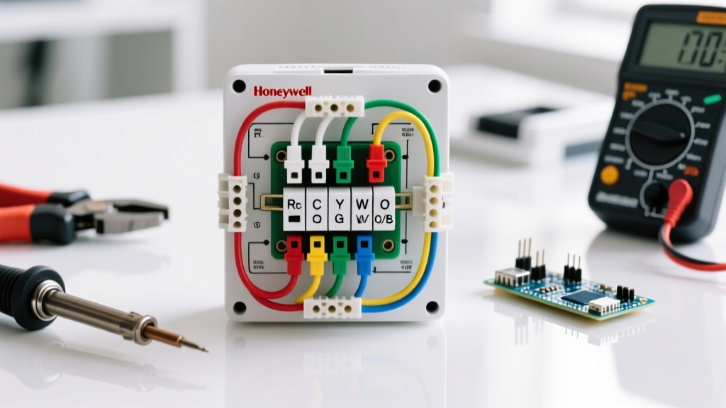
The foundation of any Honeywell thermostat wiring diagram relies on standardized terminal designations. While 18 AWG solid copper thermostat wire is the industry standard, the color coding is a convention, not a strict electrical code. Always verify the actual connections at your air handler's control board. Below is the definitive terminal matrix for 2026 Honeywell and Resideo models.
| Terminal | Standard Color | Function & Technical Details |
|---|---|---|
| R / Rc / Rh | Red | 24VAC Hot (Power). Rc is for cooling transformer, Rh is for heating. Internal jumper connects them for single-transformer systems. |
| C | Blue / Black | 24VAC Common. Completes the circuit for smart Wi-Fi thermostats. Mandatory for Honeywell T9 and T10 models. |
| W / W1 | White | Stage 1 Heat. Sends 24VAC to the furnace control board or boiler relay to initiate primary heating. |
| W2 / Aux | Black / Brown | Stage 2 / Auxiliary Heat. Engages electric resistance strips or a secondary gas valve in multi-stage systems. |
| Y / Y1 | Yellow | Stage 1 Cooling. Energizes the outdoor condenser contactor coil to start the compressor. |
| G | Green | Indoor Blower Fan. Energizes the fan relay for continuous circulation independent of heating or cooling. |
| O / B | Orange / Blue | Reversing Valve (Heat Pumps). O energizes in cool (Rheem, Ruud, Honeywell). B energizes in heat (Trane, Lennox). |
| E | Emergency | Emergency Heat. Bypasses the heat pump compressor and forces auxiliary electric strips on during system failure. |
| S1 / S2 | Shielded Pair | Outdoor Temperature Sensor. Uses a 10k ohm thermistor to lock out auxiliary heat above specific balance points. |
Common Wiring Scenarios & Diagram Logic
Understanding the diagram requires matching your specific HVAC architecture to the thermostat's sub-base terminals. Here are the two most prevalent configurations encountered in residential retrofits.
Scenario A: Conventional 1H/1C System (Gas Furnace + Central AC)
For a standard forced-air gas furnace paired with a split-system air conditioner, the wiring diagram is straightforward. You will utilize an 18/5 wire bundle. The R terminal receives 24VAC from the furnace transformer. The W terminal routes to the gas valve relay, Y routes to the AC contactor (usually via the furnace board's Y terminal), and G controls the blower. If you are installing a Wi-Fi enabled Honeywell Home T9, you must connect the C terminal. Without it, the thermostat will attempt to 'power steal' through the Y or W circuits, which can cause 'ghosting' (briefly energizing the AC contactor or furnace igniter without starting the system).
Scenario B: Heat Pump with Auxiliary Heat
Heat pump wiring diagrams for Honeywell's VisionPRO 8000 series require an 18/8 wire setup due to the additional reversing valve and auxiliary stages. The most critical decision point in this diagram is the O/B terminal configuration. According to Resideo's official technical bulletins, the default setting in the Honeywell ISU (Installer Setup) menu is 'O' (energize in cooling). If you are servicing a home with a Trane or American Standard heat pump, you must physically move the wire to the B terminal and change ISU parameter 200 to '1' (energize in heating). Failure to do so will result in the system blowing cold air during the winter and hot air during the summer.
Expert Insight: Never assume the previous installer followed standard wire color codes. In older homes, it is incredibly common to find 18/3 wire repurposed for HVAC, where Black is R, White is W, and Red is G. Always trace and label wires at the air handler control board before disconnecting the old thermostat.
The C-Wire Dilemma in Smart Thermostat Upgrades
As of 2026, smart thermostats are the baseline for energy-efficient homes, aligning with ENERGY STAR certification requirements for automated HVAC scheduling. However, older homes wired with 18/4 cable lack the dedicated Common (C) wire.
If your wiring diagram lacks a C-wire, you have two actionable solutions:
- Pull New Wire: Run a new 18/5 or 18/8 thermostat cable from the air handler to the wall plate. This costs roughly $35 for a 250ft spool of 18/8 solid copper wire but requires fishing wires through drywall.
- Install a C-Wire Adapter: Use the Honeywell THP9045A1023 C-Wire Adapter (retailing around $30). This module wires directly into your furnace control board's R and C terminals, and uses a high-frequency diode bridge to inject the common signal over the existing G (Fan) wire, freeing up the physical G wire to act as your new C-wire at the thermostat.
Troubleshooting: Failure Modes & Edge Cases
Even with a perfect wiring diagram, physical installation errors cause 90% of post-installation callbacks. Watch for these specific failure modes:
- The Blown 3A Fuse: If the thermostat display is dead and the AC/furnace is unresponsive, check the IFC board. The 3A ATO automotive fuse will be blown. This happens if the R wire's exposed copper strands touch the C wire or the grounded metal chassis during installation. Fix: Strip wires to exactly 1/4 inch (6mm) to prevent stray strands.
- Dual Transformer Isolation: In homes with separate heating (e.g., oil boiler) and cooling (e.g., central AC) systems, there are two distinct 24VAC transformers. You must remove the factory-installed R-to-Rc jumper on the back of the Honeywell thermostat. Connect Rh to the boiler's R, and Rc to the AC's R. If you leave the jumper in, you will cross-phase the two transformers, resulting in a catastrophic short circuit that will destroy both transformers.
- Short Cycling Compressors: If the AC turns on and off every 3 minutes, verify the Y wire is not touching the G wire. Additionally, ensure the compressor lockout timer (usually 5 minutes) is active in the Honeywell ISU settings to prevent liquid slugging in the compressor.
Step-by-Step Termination & Mounting
Follow this precise sequence to ensure a clean, reliable connection that complies with NFPA 70 (NEC) Article 725 regarding Class 2 remote-control circuits:
- Prep the Wires: Use wire strippers to remove exactly 1/4 inch of insulation. Do not nick the solid copper core, which creates a weak point prone to snapping inside the terminal block.
- Insert & Secure: Push the bare wire straight into the Honeywell sub-base terminal slot. Tighten the set screw with a small flathead screwdriver until snug. Give each wire a gentle 1-pound tug to ensure it is seated.
- Manage the Slack: Fold the excess wire neatly into the wall cavity. Do not cram the wires tightly against the back of the thermostat PCB, as this can trigger the internal bi-metallic temperature sensor to read artificially high, causing the system to short-cycle.
- Level and Snap: Use the integrated bubble level on the T6 PRO trim ring. Align the faceplate pins and press firmly around the edges until the retaining clips engage with an audible click.
By strictly adhering to this wiring diagram and understanding the underlying logic of the 24VAC control circuit, you ensure optimal performance, protect expensive HVAC control boards, and unlock the full energy-saving potential of modern Honeywell smart thermostats.