
The Anatomy of Multi-Location Lighting Circuits
When tackling complex residential lighting layouts, mastering the wiring diagram for 4 way switch configurations is essential for any DIY enthusiast or journeyman electrician. Unlike standard single-pole switches that simply break a hot wire, a 4-way switch acts as an intermediate reversing mechanism. It allows you to control a single lighting load from three or more distinct locations—perfect for long hallways, multi-landing staircases, or large commercial rooms with multiple entry points.
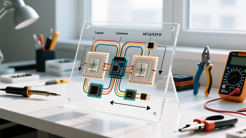
It is critical to understand that a 4-way switch cannot operate independently. According to standard electrical theory and NFPA 70 (National Electrical Code) guidelines, a 4-way switch must always be installed in series between two 3-way switches. The 3-way switches cap the ends of the circuit, connecting the power source (line) and the lighting fixture (load), while the 4-way switch sits in the middle, managing the traveler wires.
Decoding the Wiring Diagram for 4 Way Switch Terminals
If you look at a standard 4-way switch (such as the Leviton Decora 5604-2W or the Eaton 277W), you will notice it lacks the Common, Line, or Load terminal markings found on 3-way switches. Instead, the wiring diagram for 4 way switch setups relies on two pairs of traveler terminals.
- Terminal Pair A (Usually Brass): Accepts the incoming traveler wires from the first 3-way switch.
- Terminal Pair B (Usually Black or Dark): Sends the outgoing traveler wires to the second 3-way switch.
- Ground Screw (Green): Connects to the bare copper or green insulated equipment grounding conductor.
Internally, the toggle mechanism of a 4-way switch operates in two states. In the first position, it connects the travelers straight through (A1 to B1, A2 to B2). When toggled, it crosses the connections internally (A1 to B2, A2 to B1). This cross-switching capability is what allows the circuit path to be completed or broken regardless of the positions of the two flanking 3-way switches.
Step-by-Step Current Path Analysis
To truly understand the schematic, let us trace the 120V AC current path from the breaker panel to the light fixture in a standard 3-switch setup:
- Source to First 3-Way: The 120V hot (black) wire from the panel enters the Common terminal of the first 3-way switch.
- First Traveler Run: Depending on the toggle position, the current exits through one of the two traveler terminals, traveling via a 3-wire cable (often /3 Romex) to the first pair of terminals on the 4-way switch.
- The 4-Way Reversal: The current enters Terminal Pair A. The 4-way switch either passes it straight across to Terminal Pair B or crosses it. It then exits into the second set of traveler wires.
- Second Traveler Run: The traveler wires carry the current to the second 3-way switch, landing on its two traveler terminals.
- Final 3-Way to Load: If the second 3-way switch is toggled to align with the incoming active traveler, the current passes through to its Common terminal.
- Load and Return: The switched hot wire carries the current to the light fixture. The neutral wire (white) completes the circuit back to the panel.
Material Specifications and Wire Gauge Matrix
Selecting the correct wire gauge and switch rating is vital for safety and code compliance. Below is a reference matrix for standard residential 4-way switch installations as of 2026:
| Circuit Breaker | Wire Gauge (Copper) | Max Continuous Load (120V) | Recommended 4-Way Switch Model | Avg. Cost (2026) |
|---|---|---|---|---|
| 15 Amp | 14 AWG | 1,440 Watts | Leviton 5604-2W (Decora) | $12 - $16 |
| 20 Amp | 12 AWG | 1,920 Watts | Eaton 277W (Commercial Grade) | $14 - $19 |
| 15/20 Amp | 14 or 12 AWG | LED/Incandescent up to 600W | Lutron Maestro MA-S8AM (Smart) | $55 - $70 |
Critical NEC Code Compliance Mandates
When executing any wiring diagram for 4 way switch circuits, strict adherence to the National Electrical Code is non-negotiable. Mike Holt Enterprises and other industry authorities frequently highlight the following code sections during electrical inspections:
NEC 404.2 - Switching the Grounded Conductor: You must never switch the neutral (grounded) wire. All switches, including 4-way intermediaries, must exclusively break the ungrounded (hot) conductors. Switching a neutral leaves the light fixture energized even when turned off, creating a severe shock hazard during bulb changes or maintenance.
Additionally, NEC 300.3(B) requires that all conductors of the same circuit (including the hot, switched hot, neutral, and travelers) be routed within the same cable or raceway. Separating travelers into different cables or conduits can create inductive heating and dangerous electromagnetic fields, especially in commercial settings with metal framing.
Pro-Tip: Traveler Identification
Electricians frequently use colored electrical tape to maintain sanity in multi-location wiring. Wrap blue tape around all traveler wires at both ends. Wrap yellow tape around the switched hot wire leading to the fixture. This visual coding prevents the common mistake of landing a traveler on a 3-way common terminal, which is the number one cause of circuit failure in these setups.
Advanced Troubleshooting and Failure Modes
Even with a perfect schematic on paper, physical wiring errors happen. Use this diagnostic matrix to troubleshoot a malfunctioning 4-way circuit:
| Symptom | Probable Cause | Diagnostic Action |
|---|---|---|
| Light only turns on/off from one specific switch location. | The Line or Load hot wire was mistakenly wired to a traveler terminal on one of the 3-way switches. | Identify the true Line and Load using a non-contact voltage tester and multimeter; re-terminate to the Common screw. |
| Light works from Switch 1 and 3, but Switch 2 (the 4-way) does nothing. | Both incoming travelers were landed on the same pair (e.g., both on the brass screws) instead of one pair in, one pair out. | Verify that one 3-wire cable lands entirely on Pair A, and the second 3-wire cable lands entirely on Pair B. |
| Breaker trips immediately upon flipping any switch. | A traveler wire is shorted to ground, or the neutral was incorrectly routed through a switch terminal and is shorting to the hot. | Disconnect all switches, cap all wires, and perform a continuity test between hot/neutral and hot/ground to isolate the short. |
| Phantom voltage or LED fixtures flicker when off. | Induced voltage on long traveler runs or use of an incompatible dimmer on a 4-way smart circuit. | Install a Lutron LUT-MLC capacitor at the light fixture to bleed off phantom voltage. |
Modern Alternatives: Smart Switch Bypasses
As of 2026, the traditional wiring diagram for 4 way switch setups is increasingly being replaced by smart lighting ecosystems. Pulling new 3-wire traveler cables through finished walls is labor-intensive and expensive. Systems like the Lutron Caseta or Leviton Decora Smart bypass the need for physical 4-way traveler wires entirely.
In a smart setup, you wire a single smart switch at the primary power source location. The physical 4-way and secondary 3-way switches are removed, and their wall boxes are capped or converted to house wireless Pico remotes. This not only brings the installation into compliance with OSHA Electrical Safety Guidelines by reducing complex junction points, but it also enables motion sensing, scheduling, and voice control without the headache of managing crossed traveler wires.
Summary
Reading and executing a wiring diagram for 4 way switch circuits requires a methodical approach to traveler routing, strict adherence to terminal pairings, and a firm understanding of NEC safety codes. By utilizing proper wire gauges, color-coding your travelers, and understanding the internal cross-switching mechanism of the 4-way device, you can reliably control lighting from unlimited locations while maintaining a safe, code-compliant electrical system.