
The Motor Control Perspective on Water Heater Sequencing
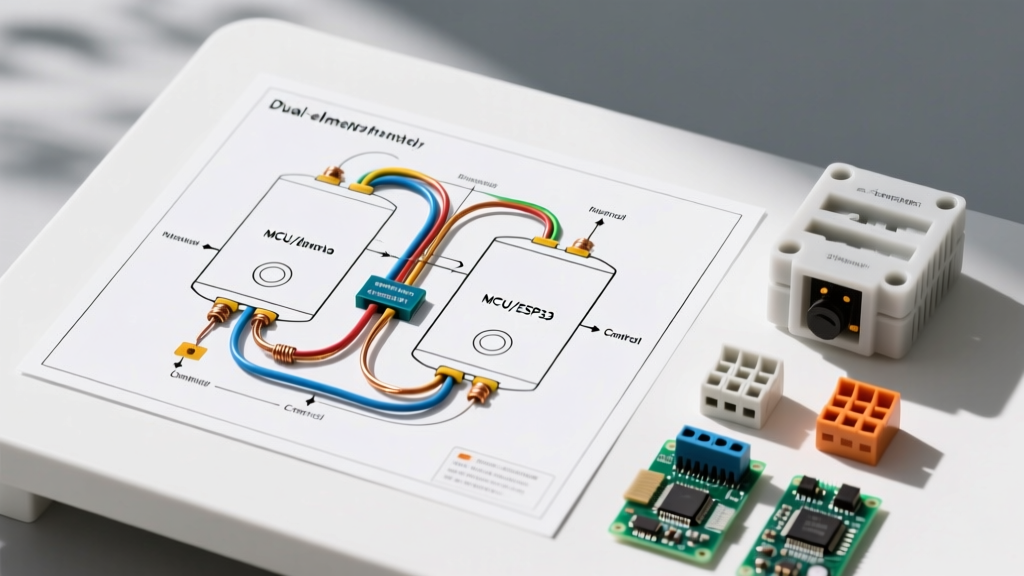
Electricians and technicians trained in industrial motor control centers (MCCs) will immediately recognize the underlying logic of a standard residential electric water heater. When you analyze a wiring diagram for dual element water heater circuits, you are not just looking at a simple heating appliance; you are looking at a sequential interlock control circuit. In motor wiring tutorials, we use interlocking relays and contactors to prevent two large inductive loads from starting simultaneously, which would cause severe voltage drop and trip main breakers. A dual-element water heater applies this exact same principle to resistive loads.
Most residential tanks utilize two 4500-watt heating elements. If both elements were to energize simultaneously, the system would draw 9000 watts (37.5 amps at 240V), requiring heavy 8 AWG copper wire and a 40-amp or 50-amp double-pole breaker. To keep installation costs down and utilize standard 10 AWG wire on a 30-amp breaker, manufacturers use a non-simultaneous (sequential) wiring topology. The upper thermostat acts as a priority interlocking relay: when the upper tank requires heat, it physically breaks the control circuit to the lower thermostat. Only when the upper tank reaches the setpoint does the 'interlock' switch states, sending line voltage down to the lower thermostat.
Core Components and 2026 Market Specifications
Before pulling wire, it is critical to understand the specific components involved. Modern water heaters rely on snap-disc thermostats with integrated Energy Cut-Off (ECO) safety limits. Below is a breakdown of the standard components, their motor-control equivalents, and current 2026 average pricing for high-quality replacements like Camco or Honeywell/Rheem OEM parts.
| Component | Specification | 2026 Avg Cost | Motor Control Equivalent |
|---|---|---|---|
| Upper Thermostat | 240V, 30A, SPDT w/ ECO | $18 - $26 | Priority Interlocking Relay |
| Lower Thermostat | 240V, 30A, SPST w/ ECO | $14 - $22 | Standard Motor Starter Coil |
| Heating Elements | 4500W, 240V, Screw-in | $12 - $18 ea | Resistive Motor Load |
| Circuit Breaker | 30A, 2-Pole, HACR rated | $10 - $16 | MCC Main Disconnect |
| Branch Circuit Wire | 10/2 NM-B (Copper) | $0.65 / ft | Feeder Cable |
Step-by-Step Wiring Diagram for Dual Element Water Heater
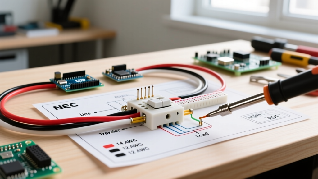
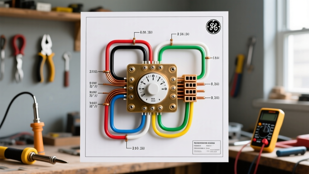
Understanding the terminal designations is crucial. Thermostats typically feature screw terminals labeled for Line (incoming power) and Load (outgoing power). Here is the precise wiring sequence, mapped out as if you were wiring a sequential motor starter.
Phase 1: Line Voltage to the Upper Thermostat (The Main Disconnect)
- L1 (Black Wire): Connect the black wire from your 10/2 NM-B branch circuit to the Line 1 terminal on the upper thermostat.
- L2 (White Wire): The white wire (which must be re-identified with black or red phase tape per NEC 200.7) serves as your second hot leg. Connect this to the Line 2 terminal on the upper thermostat, and simultaneously run a jumper wire from this terminal directly to one of the screw terminals on the Lower Heating Element.
Expert Note: In motor control, we always route one leg of the power directly to the load (the motor or element) and switch the other leg through the contactor/thermostat. This ensures that when the thermostat is open, the load is completely de-energized on the switched side, simplifying troubleshooting.
Phase 2: The Interlock (Upper to Lower Sequencing)
The upper thermostat has a set of terminals dedicated to the lower circuit. When the upper tank is cold, the internal bi-metal disc routes power to the upper element. When the upper tank is satisfied, the disc snaps to the alternate position, routing power to the lower thermostat.
- Connect a jumper wire from the Lower Load terminal on the upper thermostat to the Line 1 terminal on the lower thermostat.
- This wire only carries voltage when the upper tank has reached its target temperature.
Phase 3: Lower Element Activation
- Connect a wire from the Load terminal on the lower thermostat to the remaining screw terminal on the Lower Heating Element.
- Grounding: Connect the bare copper ground wire from the 10/2 cable to the green grounding screw on the water heater tank chassis. Do not rely on the water pipes alone for equipment grounding; a dedicated equipment grounding conductor (EGC) is mandatory per NEC Article 250.
Wire Sizing and Breaker Selection (NEC Article 422)
When sizing conductors for a water heater, we must follow the National Electrical Code (NEC) guidelines for continuous and non-continuous appliance loads. According to the NFPA NEC Article 422.13, storage-type water heaters having a capacity of 120 gallons or less must be considered a continuous load for branch-circuit sizing purposes. This means the branch circuit rating must be at least 125% of the nameplate rating.
The Math:
- Wattage: 4500W
- Voltage: 240V
- Base Amperage: 4500 / 240 = 18.75 Amps
- Continuous Load Multiplier: 18.75A x 1.25 = 23.43 Amps
Because 23.43A exceeds the rating of a 20-amp breaker, we must step up to the next standard overcurrent protection device (OCPD) size, which is 25 Amps or 30 Amps. In modern 2026 residential panels, 30A double-pole breakers are the standard, readily available choice. A 30A breaker requires a minimum of 10 AWG copper wire (rated for 30A at 60°C/75°C column in NEC Table 310.16). Using 12 AWG wire on a 30A breaker is a severe fire hazard and an immediate code violation.
Troubleshooting Common Failure Modes with a Clamp Meter
Applying motor-control diagnostic techniques makes troubleshooting a water heater incredibly efficient. Instead of blindly replacing parts, use a digital clamp meter to read the current draw on L1 and L2 at the breaker panel or the thermostat junction.
Scenario A: Upper Element Never Heats, Lower Element Runs Constantly
Diagnosis: The upper thermostat interlock is stuck in the 'satisfied' position, or the upper heating element is burnt out (open circuit).
Action: Turn off the breaker. Use a multimeter set to Ohms (Ω) to test the upper element. A healthy 4500W 240V element should read approximately 12.8 Ohms (R = V² / P -> 240² / 4500 = 12.8). If it reads 'OL' (Open Loop), replace the element. If the element is fine, replace the upper thermostat.
Scenario B: No Hot Water, Breaker is Not Tripped
Diagnosis: The Energy Cut-Off (ECO) high-limit switch has tripped. This is a safety mechanism identical to a thermal overload relay on a motor starter. It trips if the water temperature exceeds 170°F, usually due to a welded thermostat contact that failed to open.
Action: Press the red reset button on the upper thermostat. If it clicks and restores power, monitor the system. If it trips again within 24 hours, the thermostat contacts are welded shut and both thermostats must be replaced immediately to prevent tank explosion risks.
Scenario C: Breaker Trips Instantly Upon Reset
Diagnosis: A dead short to ground. This is almost always caused by a 'dry-fired' heating element. If an element is energized while not fully submerged in water, the copper tubing melts and breaches, allowing water to contact the internal nichrome wire, creating a direct short to the grounded tank chassis.
Action: Test for continuity between the element screw terminals and the grounded tank shell. Any reading other than 'OL' indicates a shorted element. Drain the tank, replace the element, and ensure the tank is 100% full before restoring power.
Final Safety and Code Compliance Notes
As highlighted by the U.S. Department of Energy's water heating guidelines, proper installation and maintenance of electric water heaters are vital not just for safety, but for system efficiency. Always ensure that the thermostat access panels are securely fastened with their original screws after wiring; missing panels expose 240V line terminals to accidental contact and violate NEC 110.28 enclosure requirements.
Furthermore, if you are upgrading an older home in 2026, verify that the neutral and ground bars in your main panel are properly bonded, and that any subpanels feeding the water heater maintain strict separation between the grounded (neutral) and equipment grounding conductors. Treat the water heater circuit with the same respect and rigorous testing protocols you would apply to a 3-phase industrial motor starter, and your installation will remain safe, code-compliant, and reliable for decades.