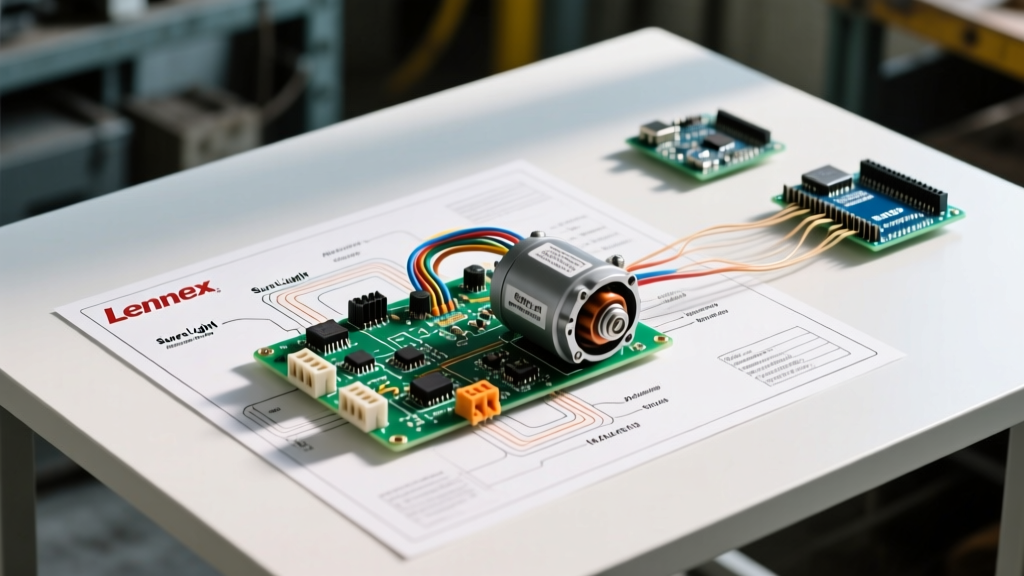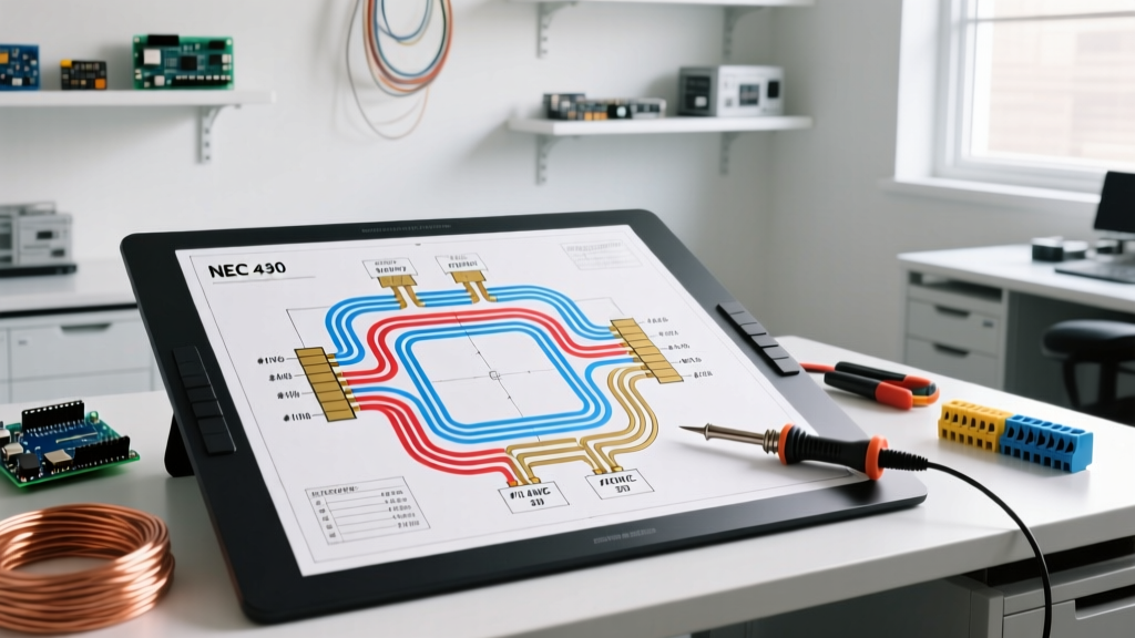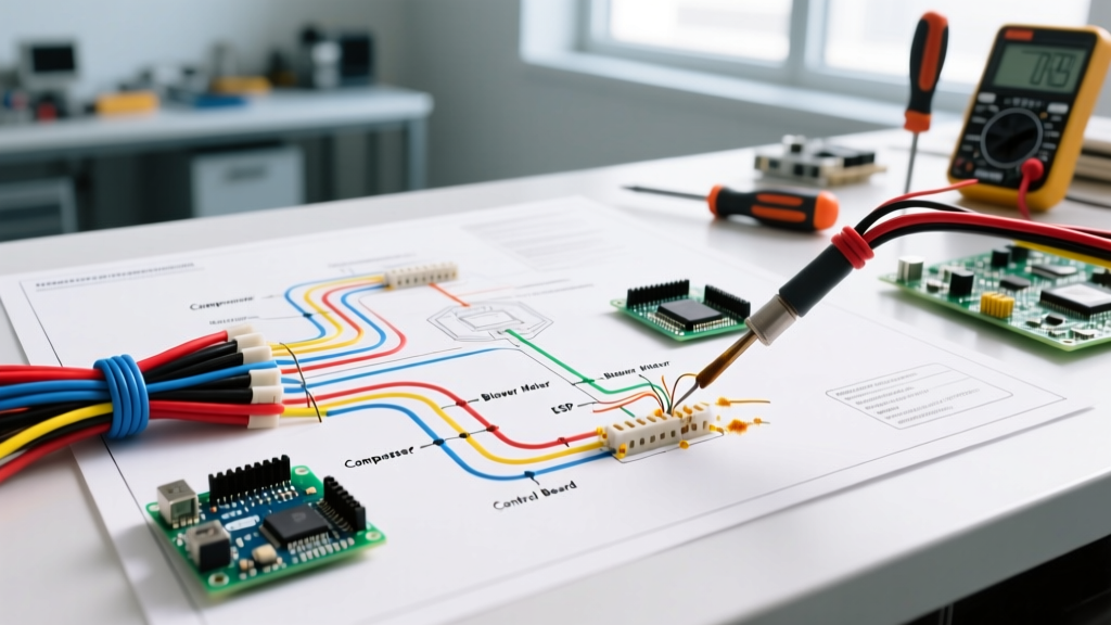

The Anatomy of a Professional Electrical Wiring Diagram Drawing
An accurate electrical wiring diagram drawing is the central nervous system of any electrical project. Whether you are designing a 400A industrial motor control center (MCC) or mapping out a 200A residential subpanel, the schematic dictates safety, compliance, and functionality. In 2026, with the adoption of smart breakers and IoT-integrated panels, the complexity of these drawings has increased exponentially. A hand-drawn sketch on grid paper is no longer sufficient for commercial or advanced DIY applications; modern projects demand rigorous CAD-based documentation that adheres to the latest NFPA 70 (National Electrical Code) standards.
This step-by-step walkthrough will guide you through the professional workflow of creating a wiring diagram, from initial software selection to final validation, ensuring your schematics are fabrication-ready and inspector-approved.
Phase 1: Selecting the Right CAD Environment for 2026
Before drawing a single line, you must choose the right software. General-purpose CAD tools like standard AutoCAD lack the intelligent, database-driven component libraries required for modern electrical design. Dedicated electrical CAD (ECAD) software automatically generates Bills of Materials (BOM), checks for wire numbering conflicts, and enforces symbol standards.
| Software Platform | 2026 Pricing Model | Best Use Case | Learning Curve |
|---|---|---|---|
| AutoCAD Electrical | ~$1,955 / year | Mid-to-large industrial control panels, complex PLC I/O mapping. | Steep (Requires prior AutoCAD knowledge) |
| EPLAN Electric P8 | ~$3,500+ (License/Maintenance) | Enterprise-level manufacturing, European IEC standard compliance, macro-driven automation. | Very Steep (Database-centric paradigm) |
| SkyCAD Electrical | Free (Standard) / ~$150 (Premium) | Residential wiring, DIY solar setups, small commercial subpanels. | Moderate (Intuitive UI, great for beginners) |
Phase 2: Step-by-Step Drawing Walkthrough
Step 1: Title Block and Border Configuration
Every professional drawing begins with the title block. For standard US projects, set your canvas to ANSI D size (22 x 34 inches). The title block must include:
- Project Name & Location: e.g., "HVAC Chiller Control Panel - Building 4".
- Drawing Number & Revision: Use a structured format like
E-101-RevB. - Sign-off Blocks: Drawn By, Checked By, and Approved By, complete with date fields.
- Standard References: Explicitly state the governing codes, such as "Designed per NEC 2026 and UL 508A".
Step 2: Power Source and Main Disconnect Mapping
Start the schematic at the top left of the page, representing the utility or upstream power source. Draw the main disconnect switch or breaker. For a standard 200A residential or light commercial service, you might specify a Square D QO200CP or an Eaton FD2200 fused disconnect.
Clearly label the incoming phases (L1, L2, L3 for 3-phase; L1, L2 for split-phase) and the Ground/Neutral bus. According to OSHA electrical safety guidelines, the main bonding jumper and the separation of the neutral and ground buses downstream of the main disconnect must be explicitly illustrated to prevent objectionable neutral current on grounding paths.
Step 3: Branch Circuit Routing and Wire Sizing
Drop down from the main distribution bus to your branch circuits. This is where precise wire sizing and color-coding annotations are critical.
- Define the Load: Calculate the full load amps (FLA). For a 1.5 HP, 230V single-phase motor, the FLA is roughly 10A.
- Size the Conductor: Per NEC Article 430.22, multiply the FLA by 1.25. (10A x 1.25 = 12.5A). Select 14 AWG THHN (rated for 15A at 90°C, though termination limits usually restrict it to 60°C/75°C ampacities).
- Size the OCPD: Select a breaker that protects the wire and accommodates motor starting inrush. A 15A or 20A inverse-time breaker is standard here.
- Annotate the Drawing: Use a wire label callout:
3/C #14 AWG THHN (BK, WH, GR)indicating a 3-conductor cable with Black (Hot), White (Neutral/Load), and Green (Ground) insulation.
Step 4: Component Placement and Symbol Standardization
When placing contactors, relays, and terminal blocks, you must adhere to a recognized symbol standard. In North America, the NEMA (National Electrical Manufacturers Association) standard is prevalent, utilizing ladder-logic style diagrams where power rails are vertical and components are drawn horizontally. In Europe and many international projects, the IEC 81346 standard is used, favoring block-style symbols and functional numbering.
Crucial Detail: Always include terminal block designations. If a wire lands on a Phoenix Contact UTTB 2.5 terminal block, label the specific node (e.g., X1:03 for Terminal Strip 1, Position 3). This eliminates hours of troubleshooting during the physical wiring phase.
Phase 3: Validation and Peer Review
A drawing is only as good as its accuracy. Before issuing a drawing for construction (IFC), run through this validation checklist:
The Voltage Drop Check: Did you account for long wire runs? A 120V circuit running 150 feet to a 12A load using 12 AWG wire will experience a voltage drop of roughly 3.6%. While under the NEC recommended 5% limit, sensitive electronics may require upsizing to 10 AWG. Always annotate voltage drop calculations on the schematic for runs exceeding 100 feet.
- Wire Number Conflict Check: Ensure no two wires share the same identification number unless they are electrically the same node.
- Short Circuit Current Rating (SCCR): Verify that the AIC (Amps Interrupting Capacity) rating of your drawn breakers exceeds the available fault current at the service entrance (typically 10kA to 22kA for residential, up to 65kA+ for industrial).
- BOM Generation: Use your ECAD software to export the Bill of Materials. Cross-reference the physical panel layout to ensure the drawn components physically fit in the specified enclosure (e.g., a Hammond 1418N436SS).
Common Edge Cases and Drafting Traps
Even experienced drafters fall victim to specific schematic errors that cause massive headaches on the shop floor. Avoid these common pitfalls:
1. The "Phantom Junction" Error
In CAD software, crossing two wires without placing a junction dot implies they do not connect. However, if layers are mismanaged or a printer drops a pixel, a crossed wire can easily be misinterpreted as a junction. Best Practice: Never cross wires on a schematic. Use a "dog-leg" or offset routing path to bypass intersecting lines entirely, eliminating all ambiguity.
2. The Floating Neutral Trap
When drawing 120V control circuits derived from a 240V transformer, drafters often forget to draw the secondary neutral back to the grounding bus or fail to illustrate the secondary overcurrent protection. Always draw the complete return path to the power source; never rely on "implied" chassis ground for AC return currents.
3. Ignoring Wire Ferrule and Crimp Specifications
A schematic should specify termination methods. Stranded wire (like Class B or Class C flexible cable) must be terminated with ferrules (e.g., Weidmüller H1.5/14 for 16 AWG) before landing in a screw-terminal breaker to prevent splaying and subsequent hotspots. Add a general note to the title block: "All stranded wire terminations must be ferruled per UL 508A standards."
Final Thoughts on Schematic Excellence
Mastering the electrical wiring diagram drawing process bridges the gap between theoretical design and safe, functional reality. By leveraging modern ECAD tools, strictly adhering to NEMA/IEC symbol libraries, and rigorously validating your branch circuits against NEC ampacity tables, you produce documentation that protects both the end-user and the installing electrician. Treat your schematic not just as a map, but as the definitive legal and technical contract of your electrical system.