
The Appeal of the 1-Wire Alternator in Off-Grid Appliance Setups
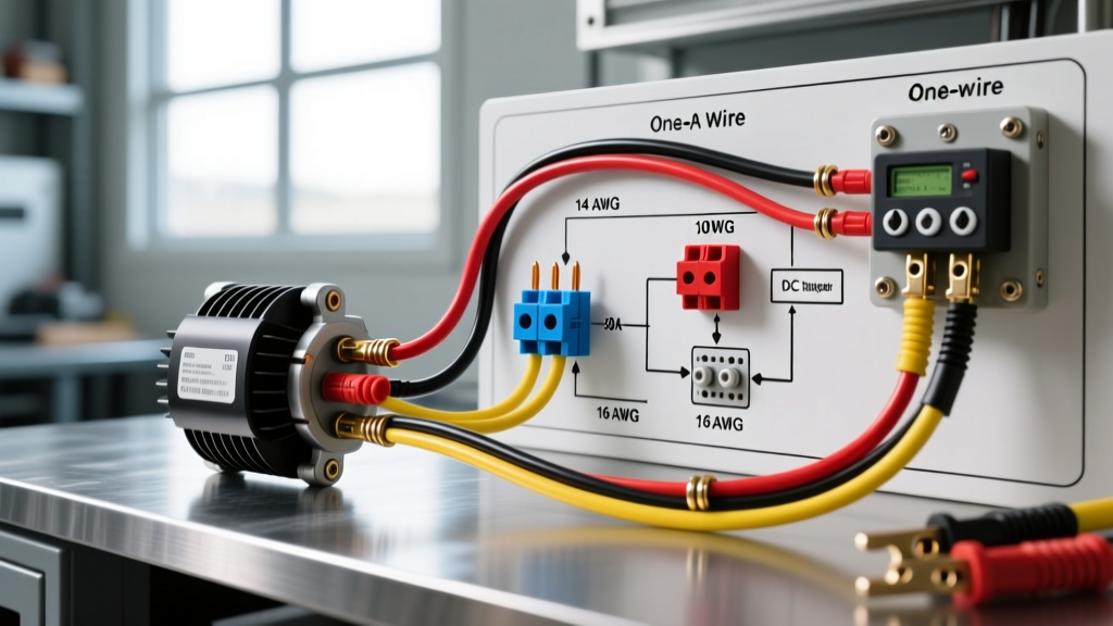
When building an off-grid cabin, converting a skoolie, or wiring a marine vessel to run heavy DC appliances and inverter loads, your charging system is the backbone of your electrical reliability. The 1-wire alternator—most commonly based on the legendary GM Delco 10SI or 12SI platforms, or modern high-output variants like the Powermaster 57293—remains a favorite among DIYers. It eliminates the complex multi-pin voltage sensing and ignition wiring of stock alternators, requiring only a single heavy-gauge cable from the alternator output stud directly to the battery bank.
However, simplicity can breed complacency. A poorly executed wiring diagram for one wire alternator installations can result in severe voltage drop, melted battery terminals, or destroyed diode bridges, especially when paired with modern high-demand appliance inverters and low-impedance LiFePO4 battery banks. This guide provides a deep-dive, appliance-focused tutorial on correctly sizing, fusing, and installing a 1-wire charging system.
Anatomy of the Core Wiring Diagram
Unlike a 3-wire setup that utilizes remote voltage sensing to compensate for voltage drop across long cable runs to a house battery bank, a true 1-wire alternator relies on internal sensing. The internal regulator reads the voltage directly at the alternator's output stud.
Expert Warning: Because the alternator senses voltage at its own output stud, any voltage drop in the main charging cable will cause the alternator to overcompensate, pushing dangerously high voltages that can fry sensitive appliance control boards or boil flooded lead-acid batteries. Minimizing cable length and maximizing wire gauge is non-negotiable.
The Basic Connection Flow
- Output Stud to Battery Positive: A single heavy-gauge marine-tinned copper cable runs from the alternator's rear output terminal to the positive busbar or battery post.
- Inline Overcurrent Protection: A fuse or circuit breaker is installed within 7 inches of the battery positive connection to protect the wire in case of a dead short.
- Grounding: The alternator case grounds through its mounting brackets to the engine block. A dedicated 4 AWG grounding strap must bridge the engine block to the vehicle chassis or the negative busbar of your house bank.
Wire Gauge, Amperage, and Fusing Matrix
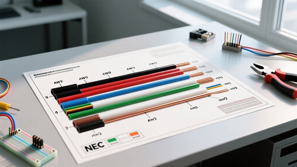
Selecting the correct wire gauge depends on the alternator's maximum amperage and the total one-way distance from the alternator to the battery bank. The National Electrical Code (NEC) and ABYC marine standards dictate that voltage drop on charging circuits should not exceed 3% (approximately 0.42V on a 14V system).
| Alternator Output | Cable Run (One-Way) | Minimum Wire Gauge (AWG) | Recommended Fuse Type & Rating | Est. Material Cost (2026) |
|---|---|---|---|---|
| 80A - 100A (e.g., Delco 10SI) | Under 5 Feet | 4 AWG | 125A ANL Fuse | $45 - $60 |
| 80A - 100A | 5 to 12 Feet | 2 AWG | 125A ANL Fuse | $75 - $110 |
| 120A - 140A (e.g., Powermaster) | Under 5 Feet | 2 AWG | 150A Class T Fuse | $90 - $130 |
| 120A - 140A | 5 to 12 Feet | 1/0 AWG | 150A Class T Fuse | $160 - $210 |
Note on Fusing: For standard AGM or flooded lead-acid batteries powering basic RV appliances, ANL fuses are sufficient. However, if your appliance bank uses Lithium Iron Phosphate (LiFePO4) batteries, you must use a Class T fuse. Lithium batteries can deliver massive fault currents that can cause ANL fuses to arc and fail to clear the short circuit safely.
Solving the Self-Excitation RPM Problem
The most common complaint when following a generic wiring diagram for one wire alternator setups is that the alternator fails to begin charging at idle. 1-wire alternators require a specific rotational speed (usually between 1,200 and 1,800 engine RPM) to generate enough residual magnetism to 'self-excite' and begin charging. If you are idling your engine to power a microwave via an inverter, you may find the battery bank draining instead of charging.
The Ignition-Triggered Relay Solution
To force excitation at low RPMs without revving the engine, advanced DIYers wire a standard 40A automotive relay (such as the Bosch 0332014150, approx. $12) into the system. While technically making it a 'two-wire' setup electrically, it preserves the 1-wire alternator's internal regulator simplicity.
- Pin 30: Connect to a switched 12V ignition source.
- Pin 87: Connect to the alternator's #1 terminal (the spade connector usually left empty on a 1-wire setup).
- Pin 85 & 86: One to ground, one to a manual dashboard toggle switch fed by 12V.
Flipping the dashboard switch momentarily sends 12V to the #1 terminal, instantly exciting the alternator field coil at idle speeds. Once charging begins, the switch can be turned off.
Integrating with Modern Lithium Appliance Banks
In 2026, the majority of high-end off-grid and RV appliance setups utilize LiFePO4 batteries. Connecting a standard 1-wire alternator directly to a large lithium bank is a recipe for alternator failure. Lithium batteries have incredibly low internal resistance and will pull the alternator's maximum output continuously, causing the alternator's stator and diodes to overheat and melt.
The DC-DC Charger Fix: Instead of running the main alternator cable directly to the lithium battery, route it to a high-amperage DC-DC battery charger, such as the Victron Energy Orion XS 12/12-50A (retailing around $190). The DC-DC charger acts as a smart load, limiting the current draw to a safe 50A while providing the precise multi-stage charging profile required by lithium chemistry. This protects your alternator while ensuring your RV refrigerator and induction cooktop inverter have a fully charged bank.
Troubleshooting Edge Cases & Failure Modes
Even with a perfect wiring diagram for one wire alternator installations, environmental and mechanical factors can introduce faults. Here is how to diagnose the most common edge cases:
- Alternator Whine in Appliance Audio/Inverters: If your off-grid entertainment system or sensitive inverter chargers emit a high-pitched whine that scales with engine RPM, you have a ground loop or failing diode trio. Ensure the engine block ground strap is free of corrosion and upgraded to at least 2 AWG flexible copper.
- Load Dump Destruction: Never disconnect the main battery cable while the engine is running to 'test' the alternator. This causes a massive voltage spike (load dump) that will instantly blow the alternator's internal voltage regulator and diodes, potentially sending 40V+ spikes back into your sensitive appliance control boards.
- Belt Slip at High Amp Draws: When a depleted battery bank demands 140A, the mechanical load on the alternator pulley is immense. A standard 1/2-inch V-belt will slip, squeal, and glaze. Upgrade to a multi-groove serpentine pulley kit (like those from Transdapt or March Performance, approx. $250-$400) to maintain grip under heavy electrical loads.
Authoritative References & Further Reading
For deeper engineering principles regarding alternator voltage sensing and marine-grade installations, consult the following industry resources:
- Mad Electrical: Alternator Tech & 1-Wire Conversions - An exhaustive breakdown of the Delco 10SI/12SI internal regulator mechanics and the historical context of 1-wire conversions.
- MarineHowTo: Alternator Voltage Sensing Explained - Critical reading for understanding why remote sensing (3-wire) is often preferred over 1-wire in large marine and skoolie battery banks to prevent appliance-damaging overvoltage.