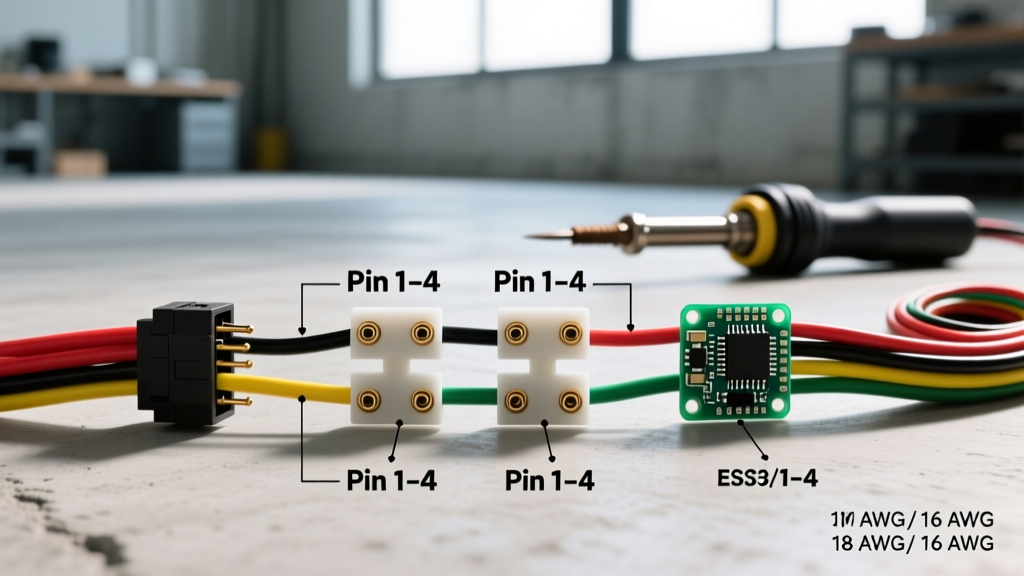

The Standard 4 Pin Wiring Diagram for Trailer Connections
Whether you are wiring a small utility trailer, a boat trailer, or a lightweight camper, the 4-way flat connector remains the undisputed standard for North American towing. Understanding the exact 4 pin wiring diagram for trailer applications is critical not just for functionality, but for legal compliance and road safety. According to the Federal Motor Vehicle Safety Standard (FMVSS) 108, all trailers must have functioning stop lamps, turn signals, and tail lamps that synchronize with the tow vehicle.
In 2026, the shift toward LED lighting and multiplexed vehicle electrical systems has changed how we approach these connections, but the fundamental 4-pin architecture remains identical. Below is the definitive reference guide for the standard US 4-way flat trailer connector.
Official 4-Way Flat Pinout Matrix
| Pin Position | Wire Color (US Standard) | Function | Typical Max Amperage (LED) | Typical Max Amperage (Incandescent) |
|---|---|---|---|---|
| Pin 1 (Exposed/Ground) | White | Chassis Ground Return | N/A (Carries total system return) | N/A (Carries total system return) |
| Pin 2 | Brown | Tail / Running / Marker Lights | 2A - 4A | 8A - 12A |
| Pin 3 | Yellow | Left Turn Signal & Stop Lamp | 2A - 3A | 6A - 10A |
| Pin 4 | Green | Right Turn Signal & Stop Lamp | 2A - 3A | 6A - 10A |
Note: The ground pin (White) is physically wider and often features an exposed male/female mating surface to ensure it connects first and disconnects last, preventing electrical arcing.
Wire Gauge Selection and Voltage Drop Calculations
Most off-the-shelf trailer harnesses (like the standard Hopkins or Curt 4-way kits) use 18 AWG wire for the ground and 16 AWG for the signal wires. While this is sufficient for a 10-foot utility trailer running modern LED lamps, it is a massive failure point for longer trailers or those still using incandescent bulbs.
The Voltage Drop Problem
Automotive electrical systems operate on a 12V nominal baseline, but alternators typically push 13.8V to 14.4V. If your wire gauge is too thin for the length of the run, voltage drop occurs. A voltage drop below 11.5V at the trailer lamp will cause incandescent bulbs to dim severely and can cause LED driver modules to flicker or shut down entirely.
- Under 12 Feet (LED Lamps): 16 AWG for all signals, 14 AWG for the white ground is perfectly adequate.
- 12 to 20 Feet (LED Lamps): Upgrade to 14 AWG for the brown running light wire (which carries the load for all side markers) and 12 AWG for the white ground.
- Over 20 Feet or Incandescent Loads: You must use 12 AWG for the brown, yellow, and green wires, and 10 AWG for the white ground wire.
Always ensure your wire insulation is rated for automotive use. Look for wire that meets SAE J1128 standards for low-tension primary cable, specifically Cross-Linked Polyethylene (XLPE) which resists heat, fuel, and abrasion far better than standard PVC.
Modern Tow Vehicles: PWM and Multiplexed Wiring
If you are wiring a trailer to a modern pickup or SUV (2020-2026 models), you cannot simply splice into the vehicle's tail light wires. Modern vehicles use Pulse Width Modulation (PWM) and multiplexed CAN-bus systems to monitor bulb health. If you tap directly into these wires, the vehicle's Body Control Module (BCM) will detect the resistance change of the trailer lights, throw a dashboard error code, and potentially cut power to the circuit entirely.
The Solution: Powered Taillight Converters
For modern vehicles, you must use a powered taillight converter. Devices like the Tekonsha 119147Z or Curt 56413 (priced between $35 and $55 in 2026) draw signaling data from the vehicle's low-current PWM wires but pull the actual high-current power directly from the vehicle's 12V battery via an inline fused line. This isolates the trailer's electrical load from the tow vehicle's sensitive BCM, preventing dashboard warnings and protecting the vehicle's wiring harness from short-circuit damage.
Step-by-Step Routing and Crimping Best Practices
A proper 4 pin wiring diagram for trailer setups is useless if the physical connections fail. Solder is generally discouraged in high-vibration trailer environments because it creates a rigid point that can snap under torsional stress. Instead, use high-quality mechanical crimps.
- Strip the Wire: Use a precision wire stripper (like the Klein Tools 11055) to remove exactly 1/4 inch of insulation. Do not nick the copper strands.
- Select the Terminal: Use adhesive-lined heat shrink ring terminals or butt connectors. The adhesive lining melts during shrinking, creating a waterproof seal that prevents capillary corrosion.
- Crimp with Force: Use a ratcheting crimper (such as the Iwiss SN-28B or Titan 11200). A ratcheting tool ensures the terminal is compressed to the exact manufacturer specification before releasing, preventing loose connections that cause high resistance and heat.
- Apply Heat: Use a dedicated heat gun (not a lighter or torch) set to roughly 300°F (150°C). Heat the center of the connector first, then move outward until the adhesive oozes slightly from the ends.
- Route and Secure: Run wires through the trailer frame's internal channels whenever possible. If running externally, use UV-resistant nylon cable ties spaced every 12 inches, and apply a protective split-loom tubing.
CRITICAL WARNING: The Grounding Fallacy
Over 80% of all trailer lighting failures are traced back to the white ground wire. Never rely on the trailer hitch ball and coupler as the ground return path. The grease, paint, and rust on the hitch create high electrical resistance. You must run the white wire from the 4-pin connector directly to the trailer frame. Sand the frame down to bare, shiny metal, attach the ring terminal using a #10 stainless steel bolt and a star washer, and coat the terminal in dielectric grease to prevent galvanic corrosion. For aluminum boat trailers, you must use a dedicated ground bus bar bolted directly to the trailer's main aluminum extrusion, as aluminum oxide acts as an insulator.
Troubleshooting Matrix: Diagnosing 4-Pin Failures
When your trailer lights malfunction, avoid guessing. Use a digital multimeter (DMM) set to DC Voltage and Continuity to systematically isolate the fault. Below is a diagnostic matrix for the most common issues encountered with 4-way flat connectors.
| Symptom | Probable Cause | Multimeter Test & Resolution |
|---|---|---|
| All trailer lights are dead. | Failed white ground connection or blown main vehicle fuse. | Test continuity between the trailer frame and the white pin. If open, clean the frame ground point. If closed, check the tow vehicle's main trailer fuse. |
| Running lights work, but turn signals do not. | Bent pins in the 4-way connector or broken yellow/green wire. | Check for 12V at the vehicle-side yellow and green pins while the turn signal is active. If present, inspect the trailer-side plug for pushed-back pins. |
| Lights dim when brakes are applied. | Voltage drop due to undersized ground wire or corroded connectors. | Perform a voltage drop test across the white wire while brakes are applied. A drop greater than 0.2V indicates a bad ground or undersized wire. |
| Turn signals cause running lights to flash. | Short circuit between brown and yellow/green wires, or bad ground. | Disconnect trailer. Test continuity between brown and yellow/green pins on the trailer plug. If continuity exists, find the pinched wire. |
| Vehicle displays 'Trailer Wiring Fault' on dash. | BCM detected resistance anomaly (common with LED upgrades). | Install a PWM-compatible load resistor or upgrade to a powered taillight converter to isolate the trailer circuit from the vehicle CAN-bus. |
Final Compliance and Safety Checks
Before taking your newly wired trailer on the road, perform a full functional test. Have an assistant stand behind the trailer while you cycle through the running lights, left turn, right turn, and hazard flashers. Ensure that the brake lights illuminate significantly brighter than the running lights (if using dual-filament incandescent bulbs like the 1157) or that the LED modules shift to their high-intensity output mode.
Compliance with FMVSS 108 lighting regulations requires that stop lamps be visible from a distance of 300 feet in normal sunlight. If your trailer is wider than 80 inches, federal law also mandates the addition of side marker lamps and clearance lamps, which must be wired into the brown running light circuit of your 4-pin diagram. Always carry a spare set of waterproof butt connectors, a ratcheting crimper, and extra fuses in your tow kit to handle roadside repairs safely and efficiently.