
Mastering the Wiring Diagram for Rheem Water Heater Troubleshooting
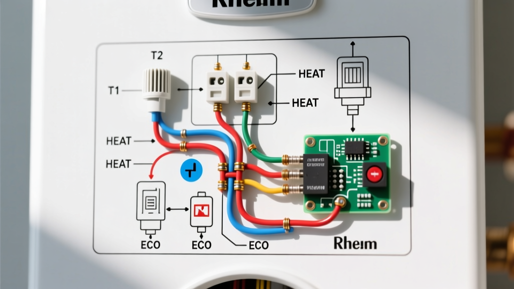
When your hot water suddenly runs cold, the wiring diagram taped to the inside of your water heater's access panel becomes your most valuable diagnostic tool. For decades, Rheem has been a dominant force in residential water heating, and their standard 240V electric models—such as the Rheem Classic Plus and Performance series—rely on a highly specific, non-simultaneous dual-element circuit. Understanding how to read a wiring diagram for Rheem water heater configurations allows you to isolate electrical faults, test components with a multimeter, and avoid unnecessary part replacements.
As of 2026, a service call from a licensed plumber or electrician to diagnose a tripped breaker or failed element typically costs between $150 and $250 before any parts are even swapped. By leveraging the manufacturer's schematic and a basic digital multimeter, DIYers can pinpoint the exact failure mode in under 20 minutes. This guide breaks down the anatomy of Rheem's electrical schematics, provides exact resistance benchmarks, and offers a step-by-step troubleshooting matrix.
Decoding the Standard 240V Non-Simultaneous Schematic
Most standard Rheem electric tank water heaters (ranging from 30 to 50 gallons) utilize a non-simultaneous (interlocked) wiring design. This means the upper and lower heating elements never receive power at the exact same time. This design prevents overloading standard residential 30-amp double-pole breakers and 10 AWG wiring.
Core Circuit Pathway
When you trace the lines on a Rheem wiring diagram, you will notice the following power flow:
- L1 and L2 (240V Supply): Power enters from the double-pole breaker via two hot wires (typically Black and Red).
- Upper Thermostat & ECO: L1 passes directly through the upper thermostat's high-limit switch (ECO - Energy Cut Off) and the upper temperature sensor. L2 passes directly to the upper heating element.
- The Interlock Switch: If the upper tank is cold, the upper thermostat closes its internal switch, sending L1 power to the upper element. Once the top half of the tank reaches the set temperature, the thermostat flips. It cuts power to the upper element and routes L1 down to the lower thermostat.
- Lower Thermostat & Element: The lower thermostat simply acts as a single-pole switch on the L1 leg. If the lower tank is cold, it closes the circuit, energizing the lower element.
Expert Insight: The ECO (High-Limit Switch) is only located on the upper thermostat in standard Rheem models. If your water heater's ECO trips, it cuts power to the entire unit, not just the top element. This is why a tripped ECO results in a total loss of hot water.
Wire Gauge, Breaker Sizing, and Load Calculations
Before testing components, you must verify that your supply circuit matches the water heater's requirements. Installing a 5500W element in a unit wired for 4500W without verifying the breaker and wire gauge is a severe fire hazard. Consult the National Electrical Code (NEC) Article 422 for continuous load appliance requirements.
| Element Wattage | Voltage | Amperage Draw | Min. Breaker Size | Min. Copper Wire Gauge |
|---|---|---|---|---|
| 3800W | 240V | 15.8A | 20A (2-Pole) | 12 AWG |
| 4500W | 240V | 18.75A | 25A or 30A (2-Pole) | 10 AWG |
| 5500W | 240V | 22.9A | 30A (2-Pole) | 10 AWG |
Note: Always size breakers to 125% of the continuous load as mandated by the NEC. A 4500W element (18.75A x 1.25 = 23.4A) requires a minimum 25A breaker, though 30A is the industry standard.
Step-by-Step Troubleshooting Matrix
Use this diagnostic matrix in conjunction with your unit's wiring diagram to isolate the faulty component. Always ensure the power is turned OFF at the main panel and verified with a non-contact voltage tester before removing access panels, as per OSHA electrical safety guidelines.
Scenario A: Total Loss of Hot Water
- Check the Breaker: Verify the 240V double-pole breaker hasn't tripped. If it has, reset it. If it trips again immediately, you have a shorted element or grounded wiring.
- Test the ECO: Locate the red reset button on the upper thermostat. If it has clicked out, press it. If it clicks and holds, the ECO tripped due to a temporary overheat or a failing lower thermostat. If it won't stay in, replace the upper thermostat (Rheem Part #SP11428 or equivalent, approx. $35-$45 in 2026).
- Verify 240V at Terminals: With power ON and extreme caution, use a multimeter set to AC Voltage. Place probes on the L1 and L2 screws of the upper thermostat. You should read 240V. If you read 0V, the issue is upstream (wiring or breaker).
Scenario B: Lukewarm Water or Rapid Depletion
If you have some hot water but it runs out in 5 minutes, your upper element is likely working, but your lower element is dead. The lower element is responsible for heating the bulk of the stored water.
- Turn off power and remove the lower access panel.
- Disconnect the two wires from the lower heating element.
- Set your multimeter to Ohms (Resistance) and touch the probes to the element's screw terminals.
- Expected Reading: ~12.8 Ω (for 4500W) or ~10.4 Ω (for 5500W).
- Fault Readings: A reading of "OL" (Open Loop) means the internal coil is broken. A reading near 0 Ω means it is shorted. Replace the element (Rheem Part #SP21363, approx. $18-$25).
Scenario C: Water is Too Hot / Scalding
If the water is dangerously hot and the ECO has not tripped, the internal contacts inside one of the thermostats have likely welded themselves together in the "closed" position, causing continuous heating.
- Diagnostic: Turn off the power. Let the tank cool. Turn the power back on and listen closely near the upper thermostat. If the tank is already hot but you hear a faint hum or click indicating the upper element is still receiving power, the upper thermostat contacts are fused. Replace the thermostat immediately to prevent tank rupture.
Multimeter Diagnostics: The Math Behind the Elements
A wiring diagram tells you where to test, but physics tells you what to expect. Many DIYers mistakenly believe any resistance reading means an element is good. You must calculate the exact expected resistance using Ohm's Law: R = V² / P.
| Element Rating | Voltage (V) | Wattage (P) | Calculation (V² / P) | Expected Multimeter Reading |
|---|---|---|---|---|
| Standard | 240V | 4500W | 57,600 / 4500 | 12.8 Ohms |
| High Output | 240V | 5500W | 57,600 / 5500 | 10.4 Ohms |
| Low Wattage | 240V | 3800W | 57,600 / 3800 | 15.1 Ohms |
Ground Fault Testing: To check if an element has burned through its copper sheath and is electrifying the water (a severe shock hazard), set your multimeter to the highest Ohms setting (e.g., 2MΩ). Place one probe on an element terminal and the other on the bare metal tank. The reading should be "OL" (Infinity). Any numerical reading indicates a grounded element that must be replaced immediately.
Exceptions: ProTerra Hybrid and Gladiator Smart Models
While the classic dual-element schematic applies to the majority of Rheem's lineup, modern high-efficiency models introduce complex control boards that alter the wiring diagram significantly.
- Rheem ProTerra (Heat Pump): These units utilize a 120V or 240V compressor alongside backup resistive elements. The wiring diagram will show a dedicated communication bus between the user interface board (UIB) and the main control board. Troubleshooting here relies heavily on LED fault codes on the control board rather than simple continuity testing. As of 2026, the U.S. Department of Energy heavily incentivizes these heat pump models, making them increasingly common in homes.
- Rheem Gladiator (Leak Detection): The Gladiator features an integrated EcoNet leak detection module and an automatic shut-off valve. The wiring diagram includes low-voltage sensor wires routed to the floor pan. If the unit refuses to heat, check the EcoNet module; a detected moisture fault will physically open the main power relay, mimicking a tripped breaker.
Final Safety Protocols & Code Compliance
Working with 240V circuits carries a high risk of fatal electrocution. Never rely solely on a wall switch or a smart breaker app to confirm power is off. Always use a CAT III or CAT IV rated multimeter to verify 0V at the thermostat terminals before touching bare wire.
Furthermore, ensure your water heater is properly grounded. The wiring diagram will indicate a green grounding screw on the tank chassis. If your home features older 2-wire (ungrounded) Romex, you must consult an electrician to run a new 10/2 with ground cable to meet modern NEC standards. Proper grounding ensures that if an element fails and electrifies the water, the breaker will trip instantly rather than waiting for a user to complete the circuit to ground.