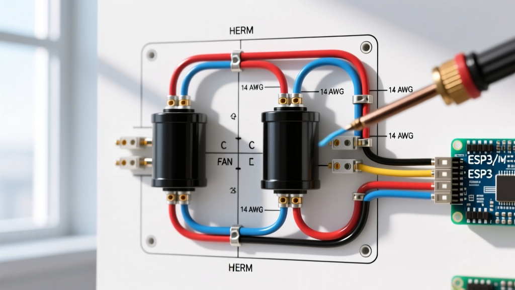

Understanding the Dual Run Capacitor Topology
In modern HVAC systems, the dual run capacitor is the unsung hero of the condenser unit. Unlike single run capacitors that only support one motor, a dual run capacitor houses two separate capacitive circuits within a single cylindrical can. This design provides the necessary phase shift for both the high-torque compressor and the condenser fan motor simultaneously. As of 2026, with the industry-wide adoption of stringent SEER2 efficiency standards, precise motor phase alignment is more critical than ever. A miswired or improperly gauged capacitor circuit will cause microfarad drift, excessive heat generation, and premature compressor failure.
When interpreting a standard wiring diagram for dual run capacitor layouts, technicians must identify three primary terminals on the top plate: C (Common), HERM (Hermetic/Compressor), and FAN. Internally, the C terminal acts as the shared junction point for both the fan and compressor start windings. Understanding how to map line voltage and component wires to these terminals—and selecting the correct wire gauge to handle the inrush and running currents—is the foundation of reliable HVAC electrical repair.
The Definitive Wiring Diagram for Dual Run Capacitor Connections
Before touching any terminals, always verify that the main disconnect switch is pulled and the unit is locked out. The wiring flow for a standard 240V split-system air conditioner follows a strict logical path:
- Line Voltage to Contactor: The 240V supply (L1 and L2) enters the contactor. When the thermostat calls for cooling, the 24V control signal energizes the contactor coil, pulling the contacts closed.
- Common (C) Terminal Feed: A wire from the T2 terminal on the contactor routes directly to the C terminal on the dual run capacitor. This provides the shared voltage baseline.
- Hermetic (HERM) Terminal Feed: A wire runs from the HERM terminal on the capacitor directly to the Start (S) winding terminal on the compressor. (The compressor's Run and Common terminals are fed directly from the contactor).
- Fan Terminal Feed: A wire runs from the FAN terminal on the capacitor to the Brown start winding wire on the condenser fan motor.
Expert Insight: Never wire the fan motor's main power feed through the capacitor. The capacitor only connects to the fan motor's dedicated start winding (usually the brown wire). The main power (often black or purple) must route directly from the contactor to the fan motor. Wiring line voltage through the FAN terminal will instantly destroy the capacitor's internal dielectric film.
Wire Gauge Selection: AWG Sizing for HVAC Circuits
Selecting the correct wire gauge is non-negotiable. According to the NFPA 70 National Electrical Code (NEC), branch circuit conductors must be sized to handle 125% of the motor's full load ampacity (FLA) plus any other continuous loads. For the short jumper wires connecting the contactor to the capacitor, and the capacitor to the motors, you must match or exceed the gauge of the branch circuit feeding the disconnect.
| Wire Gauge (AWG) | Max Ampacity (THHN/THWN-2) | Typical Breaker Size | HVAC Application (2026 Standards) |
|---|---|---|---|
| 14 AWG | 15 Amps | 15A (HACR Rated) | 1.5 Ton units, low-draw ECM fan circuits |
| 12 AWG | 20 Amps | 20A (HACR Rated) | 2.0 to 3.0 Ton standard scroll compressors |
| 10 AWG | 30 Amps | 30A (HACR Rated) | 3.5 to 5.0 Ton heavy-duty residential units |
| 8 AWG | 40 Amps | 40A (HACR Rated) | Light commercial / 5+ Ton package units |
Pro Tip: Always use stranded THHN/THWN-2 copper wire for capacitor jumpers. Solid core wire is prone to vibration-induced fatigue and micro-fractures inside the high-vibration environment of an outdoor condenser cabinet. Furthermore, ensure all spade connectors are crimped with a calibrated ratcheting crimper to prevent high-resistance hot spots.
Standard Color Code Reference for Capacitor Wiring
While the NEC mandates specific colors for line voltage (e.g., Black and Red for 240V single-phase), the internal control and component wiring of HVAC units relies on a standardized OEM color code. Adhering to these colors drastically reduces diagnostic time and prevents catastrophic cross-wiring.
- Brown: Universally designated for the FAN terminal. This wire connects the capacitor to the fan motor's start winding.
- Blue or Yellow: Typically used for the HERM terminal, routing to the compressor's start winding. (Carrier/Bryant often use Yellow, while Trane/Lennox frequently use Blue).
- Black or Red: Used for the C (Common) terminal feed originating from the T2 side of the contactor.
- Purple: Often found as the main hot leg feeding the fan motor directly from the contactor (bypassing the capacitor).
If you are replacing a degraded OEM harness, use 18 AWG or 16 AWG stranded wire for the control/thermostat lines, but strictly adhere to the 12 or 10 AWG requirements for the high-voltage capacitor jumpers outlined in the table above.
Real-World Failure Modes and Edge Cases
Even with a perfect wiring diagram for dual run capacitor setups, components fail. In 2026, the most common failure modes we diagnose in the field include:
- Microfarad Drift: Capacitors are rated with a tolerance, typically ±5% or ±6%. A 35/5 µF capacitor that drops below 32.9 µF on the HERM side will cause the compressor to draw excessive locked rotor amps (LRA), eventually tripping the internal thermal overload. Always test with a dedicated capacitance meter (like the Fluke 116 or Fieldpiece SC260), not just a standard multimeter.
- Dielectric Venting: If the ambient temperature inside the condenser cabinet exceeds 158°F (70°C), the internal metallized polypropylene film breaks down, generating gas. The capacitor's top dome will bulge, and the pressure interrupter will sever the internal connection. Ensure the condenser coil is clean to maintain proper airflow and keep cabinet temps down.
- Spade Terminal Corrosion: Coastal environments cause rapid galvanic corrosion on the 1/4" and 3/16" quick-connect spades. This increases resistance, creating a voltage drop that mimics a weak capacitor. Clean terminals with a fiberglass scratch pen and apply a dielectric grease (like Noalox) to prevent recurrence.
Safety Protocols and Discharge Procedures
A disconnected dual run capacitor can retain a lethal 440VAC charge for weeks. The OSHA Electrical Safety Standards strictly mandate verifying a zero-energy state before servicing. Never use a flathead screwdriver to short the terminals. This 'pop' method causes microscopic tears in the capacitor's internal foil windings, guaranteeing a premature failure, and poses a severe arc-flash risk to the technician.
The Correct Discharge Method: Use a purpose-built capacitor discharge tool or a 20,000-ohm, 5-watt wirewound resistor attached to insulated jumper leads. Bridge the resistor across the C and HERM terminals for 5 seconds, then repeat across the C and FAN terminals. Finally, verify 0V with a CAT III rated multimeter. For more on maintaining system efficiency and safety, refer to the U.S. Department of Energy HVAC Maintenance Guidelines.
Frequently Asked Questions
Can I use a 45/5 µF capacitor to replace a 40/5 µF capacitor?
No. While the voltage rating can be higher (e.g., using a 440VAC cap to replace a 370VAC cap), the microfarad (µF) rating must match the OEM specification exactly. A higher µF rating will over-torque the motor windings, causing excessive heat and insulation breakdown, while a lower rating will result in sluggish starting and high amp draw.
Why does my new AmRad or TITAN capacitor have 4 terminals instead of 3?
Some premium heavy-duty capacitors feature quad-blade terminals (e.g., four C terminals, two HERM, two FAN) to accommodate multiple wires without stacking spade connectors. Stacking more than two wires on a single 1/4" spade reduces the clamping force, leading to arcing. The extra terminals are internally bridged; simply distribute your wires across the matching labels.
What happens if I wire HERM and FAN backward?
Swapping the HERM and FAN wires means the compressor's start winding receives the smaller 5 µF phase shift, while the fan receives the massive 35 µF shift. The fan motor will likely overheat and shut down on internal thermal overload within minutes, and the compressor will fail to start, humming loudly until the breaker trips. Always trace and label wires before removing the old capacitor.