
Decoding the Simple Electrical Wiring Diagram for Under-Sink Appliances
Wiring a kitchen sink area requires balancing high-draw appliances on limited circuit space. When tackling under-sink wiring, a simple electrical wiring diagram is your best defense against catastrophic failure, nuisance tripping, and code violations. The most efficient and code-compliant method for powering a hardwired dishwasher and a switched garbage disposal in 2026 is utilizing a Multi-Wire Branch Circuit (MWBC) feeding a split-tab duplex receptacle.
Unlike standard single-load circuits, this configuration shares a single neutral wire between two 120V hot legs on opposing phases. This guide breaks down the exact schematic, material requirements, and critical failure modes associated with this specific appliance wiring tutorial.
Anatomy of the Split-Receptacle Schematic
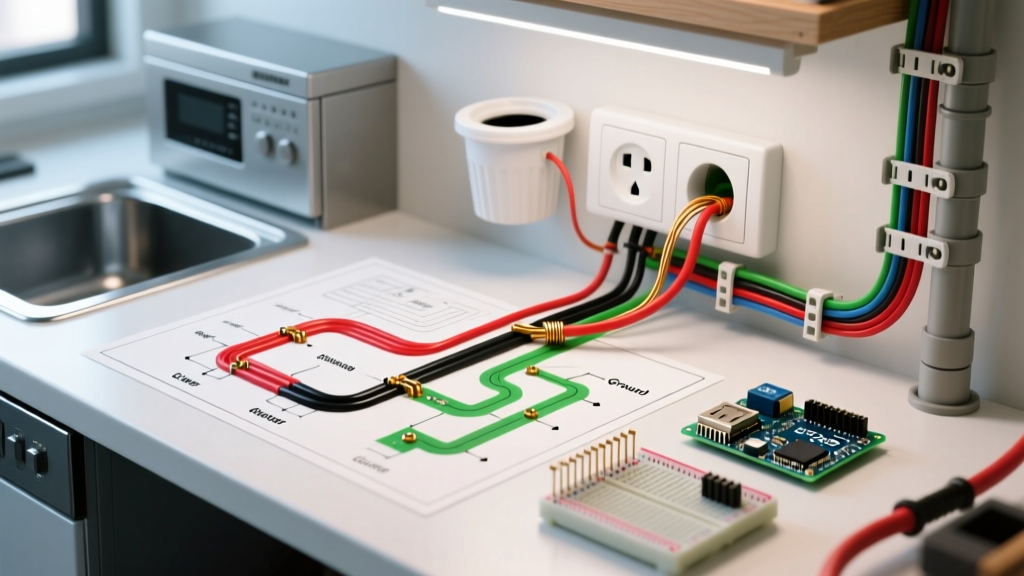
Before pulling any 12/3 NM-B cable, you must understand how to read the simple electrical wiring diagram for a split receptacle. The diagram relies on three core principles:
- The Brass Fin (Hot Side): A standard duplex receptacle has a brass screw side (hot) and a silver screw side (neutral). To feed the dishwasher continuously and the disposal via a wall switch, the brass connecting fin between the top and bottom brass screws must be physically snapped off.
- Opposing Phases (MWBC): The black wire connects to Line 1 (Phase A), and the red wire connects to Line 2 (Phase B) of a 240V double-pole breaker. This ensures the shared white neutral only carries the unbalanced load, not the sum of both appliances.
- Switched vs. Continuous: The top half of the receptacle (fed by the red wire) is routed through a 20A single-pole switch for the garbage disposal. The bottom half (fed by the black wire) remains continuously hot for the dishwasher.
2026 Material & Component Requirements
Using undersized components or outdated breakers is a leading cause of residential electrical fires. Below is the precise bill of materials required for a modern, NEC-compliant installation.
| Component | Specific Model / SKU | Est. 2026 Cost | Purpose & Code Requirement |
|---|---|---|---|
| 20A Double-Pole Breaker | Square D HOM220CP | $18.50 | Provides simultaneous disconnect (NEC 210.4) and opposing phases. |
| 12/3 NM-B Cable | Southwire 12/3 Romex | $0.95 / ft | Handles 20A load; includes black, red, white, and bare ground. |
| 20A Duplex Receptacle | Leviton TBR-20 (TR) | $7.25 | Tamper-resistant; features breakable brass fin for split wiring. |
| 20A Toggle Switch | Leviton 1221-2W | $6.50 | Controls the garbage disposal; rated for motor loads. |
Critical NEC Codes Governing This Diagram
According to the National Fire Protection Association (NFPA 70), specifically the National Electrical Code (NEC), you must adhere to the following when executing this diagram:
NEC Article 210.4(B) - Disconnecting Means: Each multiwire branch circuit shall be provided with a means that will simultaneously disconnect all ungrounded conductors at the point where the branch circuit originates. This mandates the use of a double-pole breaker or approved handle ties.
Furthermore, the Occupational Safety and Health Administration (OSHA) emphasizes that all equipment grounding conductors must be spliced and pigtailed to the receptacle, ensuring that removing the device does not break the ground path to downstream equipment.
Step-by-Step Appliance Wiring Tutorial
Step 1: Panel Preparation and MWBC Setup
Shut off the main breaker. Install the Square D HOM220CP 20A double-pole breaker into your panel. Connect the black and red wires of your 12/3 NM-B cable to the two brass breaker terminals. Connect the white neutral to the neutral bus bar and the bare copper to the ground bus bar. Never use two separate single-pole breakers without a handle tie; this violates the simultaneous disconnect rule and creates a lethal shock hazard during maintenance.
Step 2: Breaking the Receptacle Tab
This is the most common point of failure. Take your Leviton TBR-20 receptacle and locate the small brass fin connecting the two hot (brass) screws. Using a pair of needle-nose pliers, bend the fin back and forth until it snaps off completely. Do not break the silver fin on the neutral side; the neutral must remain shared. Verify the separation with a multimeter on continuity mode.
Step 3: Terminating the Split Receptacle
- Ground: Pigtail the bare copper ground wire to the green grounding screw on the receptacle.
- Neutral: Connect the white 12/3 neutral wire to one of the silver screws. (If feeding downstream, use a wire nut to pigtail the neutrals).
- Continuous Hot (Dishwasher): Connect the black 12/3 wire to the bottom brass screw.
- Switched Hot (Disposal): Connect the red 12/3 wire (returning from the wall switch) to the top brass screw.
Step 4: Wiring the Disposal Switch
At the switch box, the red wire from the panel enters the bottom terminal of the Leviton 1221-2W switch. A second red wire (the switch leg) exits the top terminal and travels to the top brass screw of the split receptacle. Ensure the white neutral simply passes through the switch box via a wire nut without connecting to the switch itself.
Advanced Troubleshooting: Edge Cases & Failure Modes
Even with a simple electrical wiring diagram, deviations in execution lead to severe consequences. Below are the specific failure modes associated with this setup:
Failure Mode 1: The "Floating Neutral" Catastrophe
If the shared white neutral wire becomes disconnected or breaks at the panel, the MWBC reverts to a 240V series circuit. Instead of 120V, your dishwasher and garbage disposal will experience up to 240V across them, depending on their relative impedances. This will instantly destroy the appliance control boards and melt internal wiring. According to the Copper Development Association, ensuring torque-screwdriver verified terminations at the neutral bus bar is the only way to prevent this thermal failure.
Failure Mode 2: Instant Breaker Trip Upon Energizing
If the 20A double-pole breaker trips the millisecond you turn it on, you likely forgot to snap off the brass fin on the receptacle. By leaving the fin intact, you have directly tied Phase A (Black) to Phase B (Red), creating a 240V dead short. Remove the receptacle, verify the fin is removed, and inspect the breaker for internal damage before resetting.
Failure Mode 3: Nuisance Tripping on Motor Startup
Garbage disposals (typically 1/2 HP to 3/4 HP) draw high inrush current (Locked Rotor Amps) upon startup. If you are using a standard thermal-magnetic breaker and the disposal is on the same leg as a running dishwasher, the combined transient load may exceed the breaker's magnetic trip curve. Upgrading to a Square D HOM220HID (HID/Motor rated breaker) provides a higher magnetic trip threshold, accommodating motor inrush without nuisance tripping.
Frequently Asked Questions
Can I use 14/3 NM-B wire on a 15A double-pole breaker for this diagram?
While 14 AWG copper is rated for 15A, modern kitchen appliance loads (especially high-efficiency dishwashers with internal water heaters) frequently draw 10-12A continuously. Using 12/3 NM-B on a 20A breaker provides a 20% thermal headroom, preventing voltage drop and wire heating inside enclosed cabinetry.
Does the garbage disposal require a GFCI receptacle?
NEC 2023 and 2026 updates expanded GFCI requirements to all 125V through 250V receptacles supplied by 15A or 20A branch circuits in kitchens. However, hardwired appliances connected via a cord-and-plug to a split receptacle under the sink must be GFCI protected. To achieve this without using a bulky GFCI split-receptacle (which do not exist in standard form factors), install a 20A Double-Pole GFCI breaker (e.g., Square D HOM220GFIC) at the panel instead of a standard breaker.