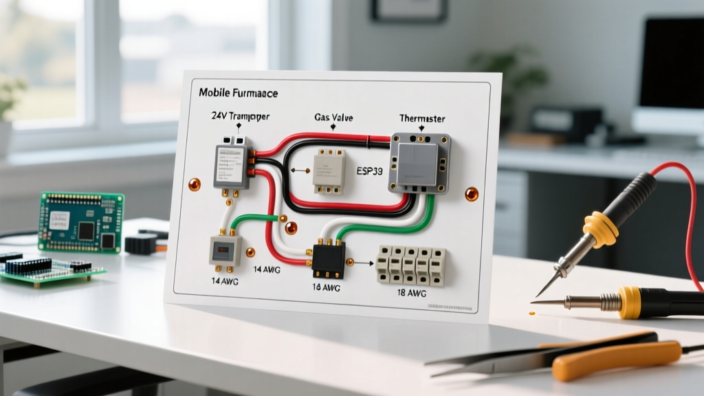

Understanding HUD-Code vs. Residential Furnace Wiring
When planning the electrical infrastructure for a manufactured home, treating the HVAC system like a standard residential setup is a critical error. Mobile home furnaces, such as the widely installed Miller CMF-80 downflow or the Nordyne Intertherm M1 series, are governed by strict federal building codes rather than just local residential codes. According to the U.S. Department of Housing and Urban Development (HUD) 24 CFR Part 3280, manufactured home heating systems must meet specific clearance, venting, and electrical bonding requirements that fundamentally alter how you read and execute the wiring diagram for mobile home furnace installations.
Unlike site-built homes where furnaces often sit in a basement with ample space for junction boxes and flexible conduit routing, mobile home furnaces are typically zero-clearance, sealed-combustion units installed in dedicated, cramped closets. This physical constraint means the wiring diagram for mobile home furnace setups prioritizes compact terminal blocks, integrated control boards, and strict separation of high-voltage (120V AC) and low-voltage (24V AC) pathways to prevent electromagnetic interference and fire hazards.
Critical Safety Warning: Always disconnect the main branch circuit breaker before opening the furnace blower compartment. Mobile home furnaces often utilize a single 120V disconnect switch located inside the blower door panel. Verify zero voltage at the control board with a CAT III multimeter before touching any terminals.
High-Voltage Supply: Breaker Sizing and Wire Gauge Planning
The first step in interpreting the wiring diagram for mobile home furnace applications is identifying the high-voltage power supply requirements. Most 80,000 to 100,000 BTU mobile home gas furnaces draw between 9 and 12 amps at peak operation (blower motor startup plus hot surface igniter draw). However, the National Electrical Code (NEC) Article 550 dictates specific overcurrent protection rules for manufactured homes.
In 2026, the standard practice for a 12-amp mobile home furnace circuit is a 15-amp or 20-amp AFCI/GFCI dual-function breaker, depending on the manufacturer's minimum circuit ampacity (MCA) listed on the data plate. Below is the planning matrix for high-voltage wiring:
| Furnace MCA Rating | Breaker Size | Wire Gauge (NM-B) | Max Run Length (3% Drop) | Est. 2026 Material Cost |
|---|---|---|---|---|
| 10 Amps or less | 15A Dual-Function | 14 AWG (14/2 w/ Ground) | 55 Feet | $0.55 / linear foot |
| 11 to 15 Amps | 20A Dual-Function | 12 AWG (12/2 w/ Ground) | 70 Feet | $0.75 / linear foot |
| 16 to 20 Amps (Elec Heat) | 30A Standard | 10 AWG (10/2 w/ Ground) | 60 Feet | $1.15 / linear foot |
Always route the 120V supply through the designated high-voltage knockouts on the furnace casing. Never run 120V line wiring through the low-voltage thermostat grommets, as this violates NEC 300.20 and creates a severe shock hazard at the thermostat wall plate.
Decoding the Control Board and Thermostat Terminals
The heart of the wiring diagram for mobile home furnace systems is the integrated control board or terminal strip. Modern units use a printed circuit board (PCB) that manages the ignition sequence, blower delays, and safety lockouts. When planning your low-voltage wiring, you must map the thermostat wires to the correct board terminals.
- R (Red): 24V AC power from the transformer. This is the hot leg of the control circuit.
- W (White): Call for heat. Completes the circuit to the gas valve and initiates the ignition sequence.
- Y (Yellow): Call for cooling. Sends 24V to the outdoor condenser contactor (if a split system is installed).
- G (Green): Fan control. Energizes the blower relay for continuous or intermittent fan operation.
- C (Blue/Black): Common wire. The return path for the 24V circuit. Essential for powering modern Wi-Fi smart thermostats without draining internal batteries.
According to the U.S. Department of Energy, upgrading to a smart thermostat can yield significant energy savings, but mobile home furnaces often lack a pre-wired C-wire. If your wiring diagram does not show a C-terminal connected to the thermostat bundle, you must pull a new 18/5 AWG thermostat cable from the control board to the wall plate to support 2026-era smart climate controls.
Blower Motor Speed Taps: The Most Common Wiring Error
Permanent Split Capacitor (PSC) blower motors are standard in mobile home furnaces. The wiring diagram will show multiple speed taps originating from the motor and terminating either on the control board or a manual speed selector block. Misinterpreting these taps is the number one cause of post-installation high-limit switch trips.
Mobile home ductwork is notoriously restrictive, often utilizing flat, rectangular trunk lines under the floor chassis. This creates high static pressure. To compensate, the wiring diagram for mobile home furnace setups typically mandates specific speed taps to ensure adequate CFM (Cubic Feet per Minute) without overheating the heat exchanger.
| Wire Color | Speed Setting | Typical Application | CFM Target (80k BTU) |
|---|---|---|---|
| Black | High | Cooling (AC) | 1200 - 1400 CFM |
| Blue | Medium-High | Heating (Standard Duct) | 1000 - 1100 CFM |
| Red | Medium-Low | Heating (Low Static) | 800 - 900 CFM |
| White | Common | Neutral/Return Path | N/A |
Expert Insight: If you wire the Black (High) tap for the heating cycle, the furnace will move too much air, potentially causing flame rollout or poor efficiency. If you wire the Red (Low) tap for heating in a restrictive under-floor duct system, the heat exchanger will overheat, tripping the high-limit switch within 90 seconds of ignition. Always default to the manufacturer's specific speed tap chart located on the inside of the blower access door.
Safety Interlocks: Limit Switches and Rollout Sensors
A crucial, often overlooked section of the wiring diagram for mobile home furnace installations is the safety interlock series circuit. Because mobile homes experience more structural flexing and vibration during transport and high winds than site-built homes, wire connections to safety switches can loosen over time.
The high-limit switch, auxiliary limit switch, and flame rollout sensors are wired in series with the 24V gas valve circuit. If any one of these switches opens due to excessive temperature, the 24V path to the gas valve is broken, shutting down the burners while leaving the blower running to cool the heat exchanger.
When planning your installation, inspect the spade connectors on these limit switches. In 2026, best practice dictates using a crimping tool to tighten any loose female spade connectors before finalizing the wiring. A loose connection on a rollout switch will cause intermittent, unexplainable furnace lockouts that are incredibly difficult to troubleshoot once the unit is buttoned up.
Pre-Installation Planning Checklist
Before pulling wire or mounting the furnace, complete this installation planning checklist to ensure your execution matches the wiring diagram for mobile home furnace requirements:
- Verify Chassis Grounding: Ensure the furnace chassis is bonded to the mobile home's main grounding bus bar using a minimum 8 AWG copper wire, as required by HUD standards.
- Calculate Voltage Drop: Measure the exact distance from the main panel to the furnace closet. If the run exceeds 60 feet on a 15A circuit, upgrade to 12 AWG wire to prevent voltage drop that can cause the hot surface igniter to fail to reach ignition temperature.
- Map the Thermostat Cable: Confirm you are using 18/5 AWG solid copper thermostat wire. Do not use stranded wire, as it can fray and cause short circuits at the tight terminal screws of mobile home control boards.
- Plan the Condensate Drain (if applicable): If your mobile home furnace is a high-efficiency condensing model (90%+ AFUE), plan the PVC condensate drain route and ensure the condensate trap is wired correctly to the pressure switch circuit.
- Document the Speed Taps: Take a high-resolution photo of the factory wiring diagram and the current motor speed tap configuration before disconnecting the old unit. This serves as your baseline reference for airflow calibration.
By treating the wiring diagram for mobile home furnace setups not just as a schematic, but as a comprehensive installation planning tool, you ensure a safe, code-compliant, and highly efficient heating system capable of withstanding the unique environmental demands of manufactured housing.